Library of Failures
A library of classical material failure examples. Use the filter options to refine your search.
Overheated Bearing Shells
The white-metal-coated steel bearing shells on a crankshaft had failed during testing. Examination revealed that the core of the ...
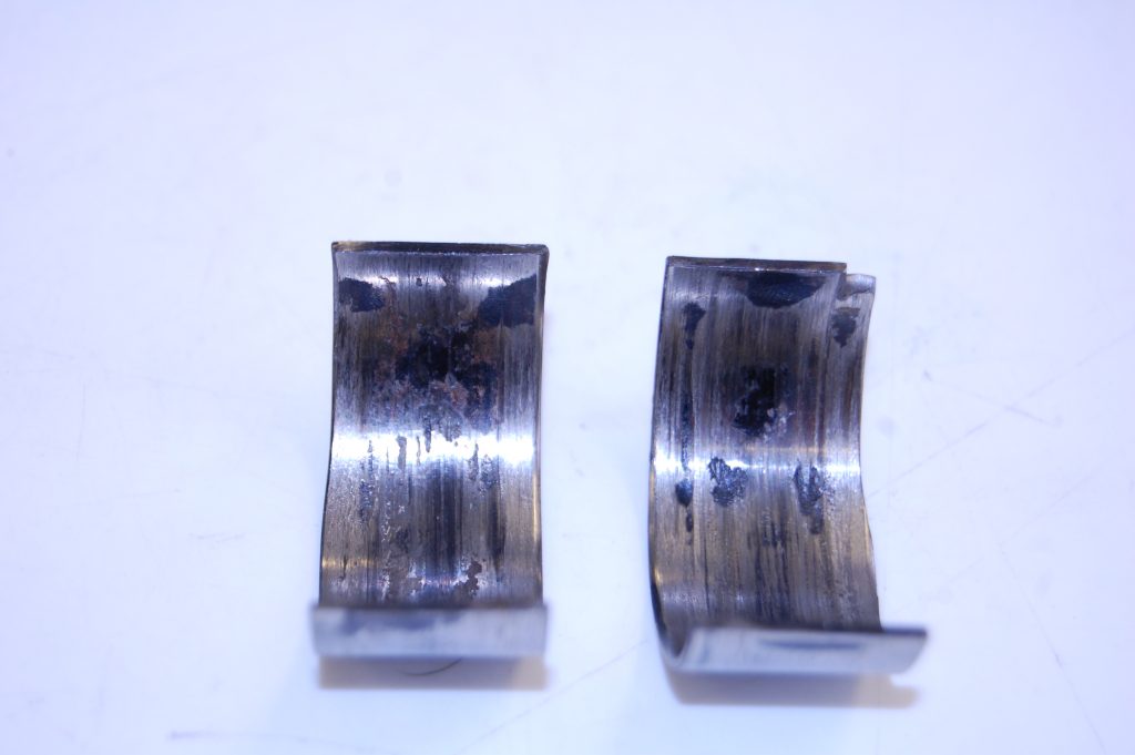


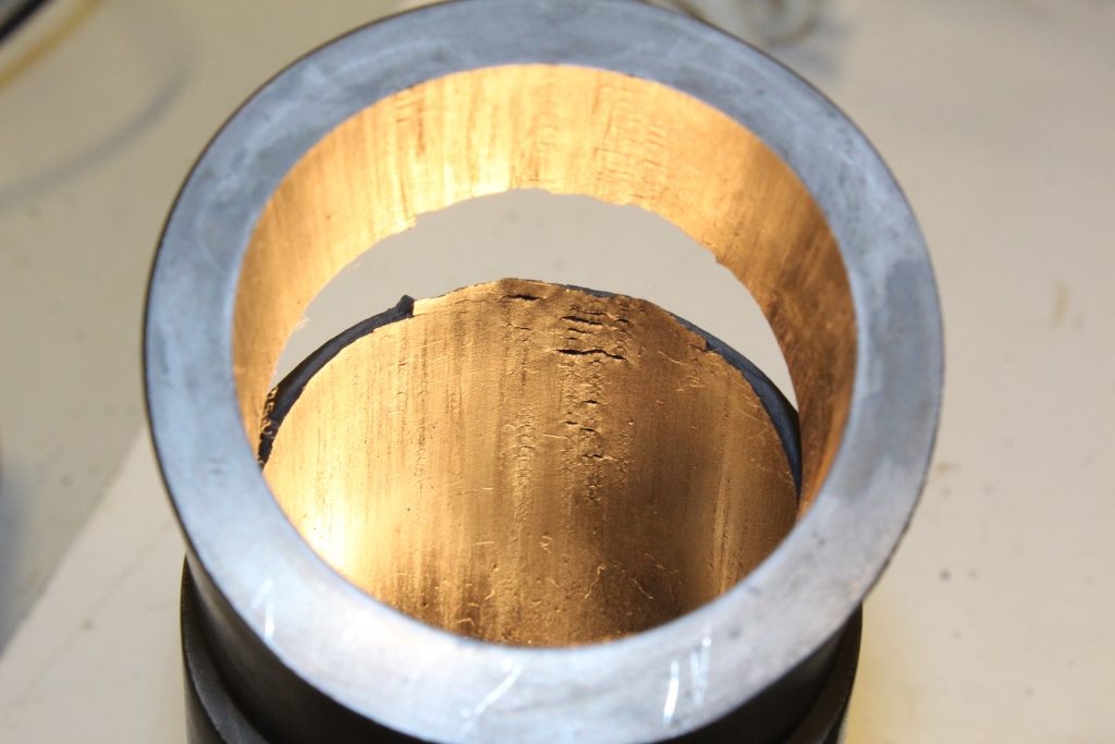
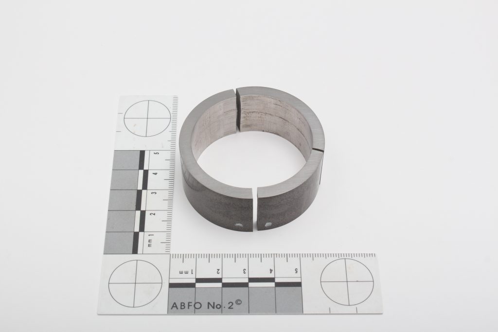
The bearing shells as received displaying of scoring and pitting.


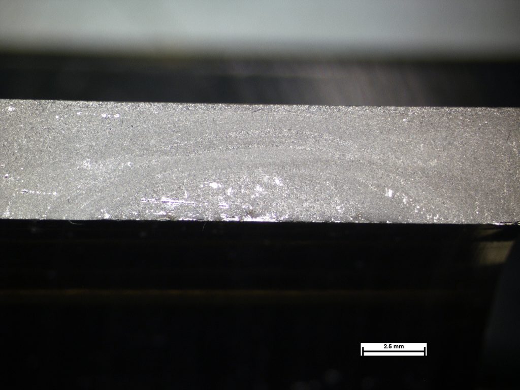
The working surface of the shell with the liquation cracks running at a right angle to the direction of rotation.
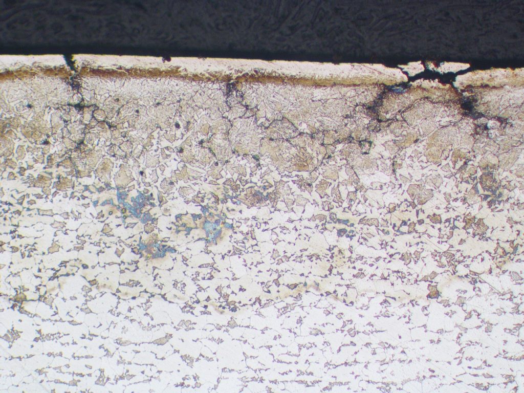


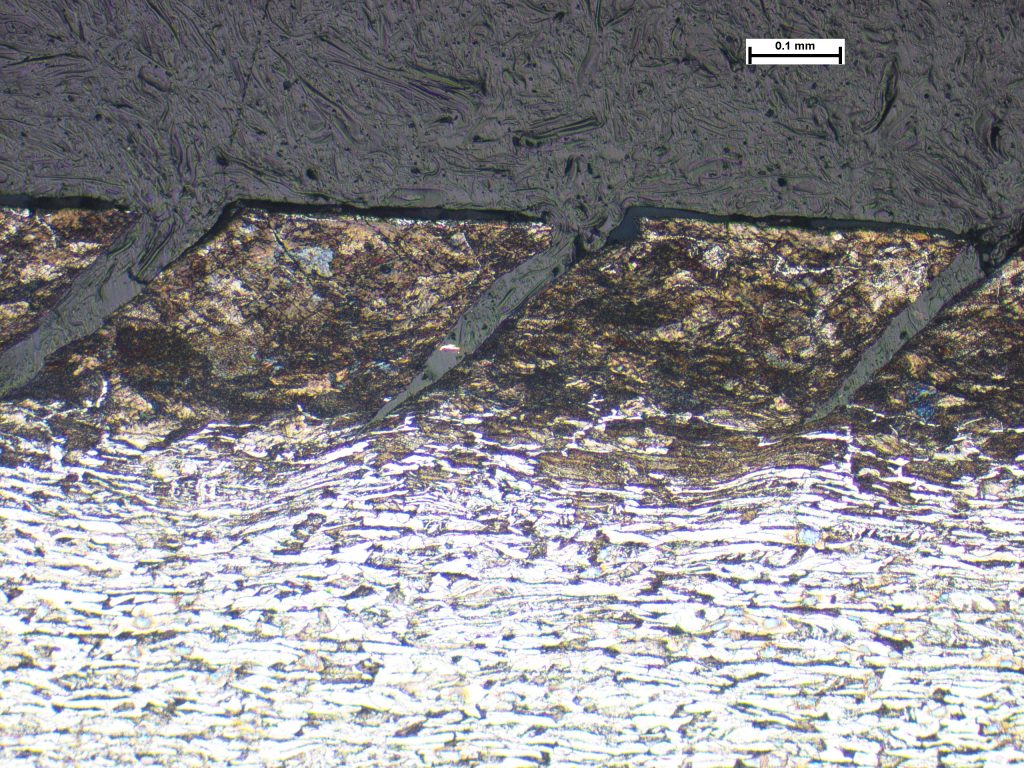
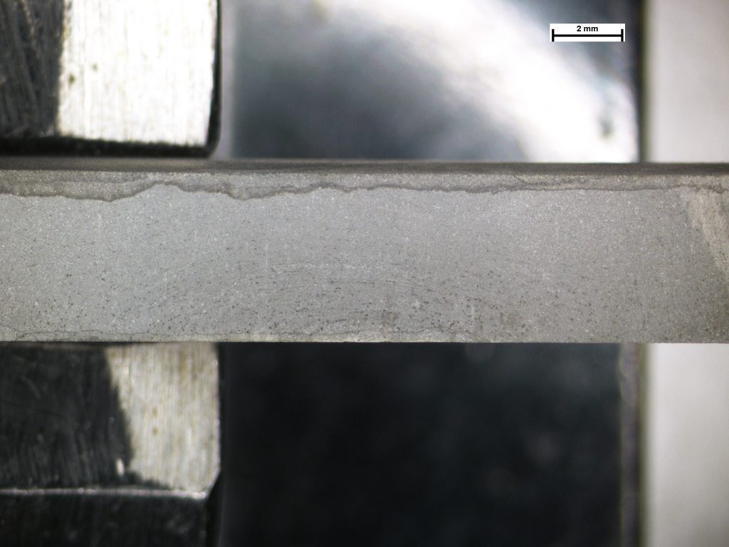
Photomicrograph of the working surface displaying a banded white layer and heat damaged bainitic microstructure below. The liquation (hot) cracking can also be seen at the top propagating in an intergranular path.
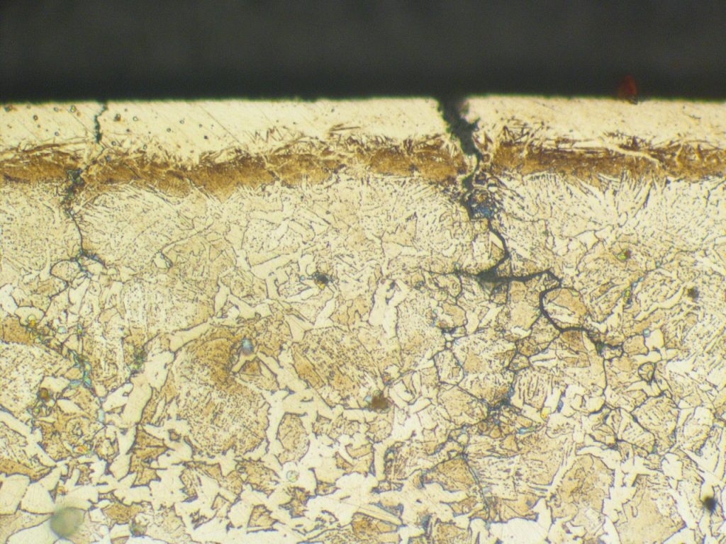


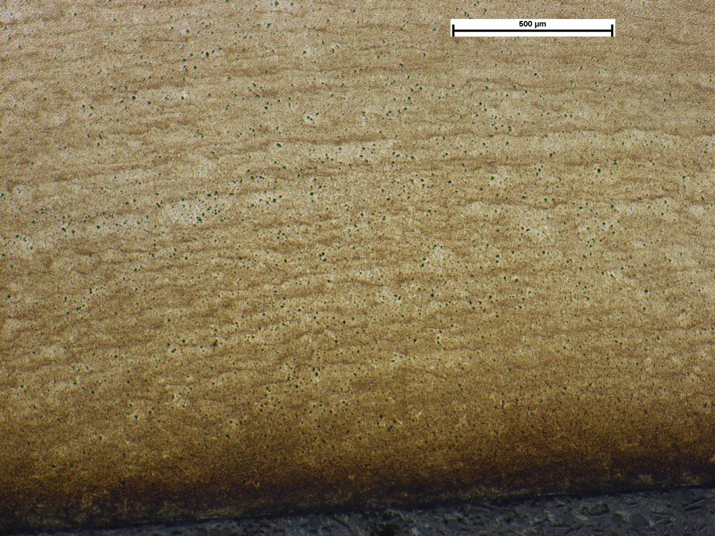
The liquation crack at 500x magnification displaying intergranular propagation
Overheated Bearing Shells
The white-metal-coated steel bearing shells on a crankshaft had failed during testing. Examination revealed that the core of the bearing had a ferrite and pearlite microstructure, but in some areas the working surface has been transformed to bainite. This phase only forms above the transformation temperature of the low alloy steel (around 723°C) which indicated the region had been subjected to extreme localised overheating, and probably in the last stage of engine seizure. Intergranular cracks were observed to have propagated into the steel with indications of crack opening. The form of the cracks was indicative of hot cracking (liquation cracking) with the crack opening indicative of the relief of residual stress that was probably a consequence of the rapid heating and cooling of the bearing shell.
316L Process Pipe Corrosion
Three weeks after installation, 316L pipework started to leak from pinhole defects. These were predominantly located at welds tha...
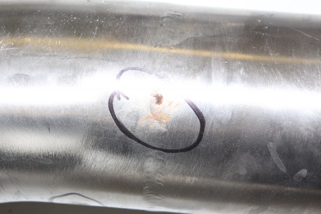


Area of leakage, showing orange-brown staining.
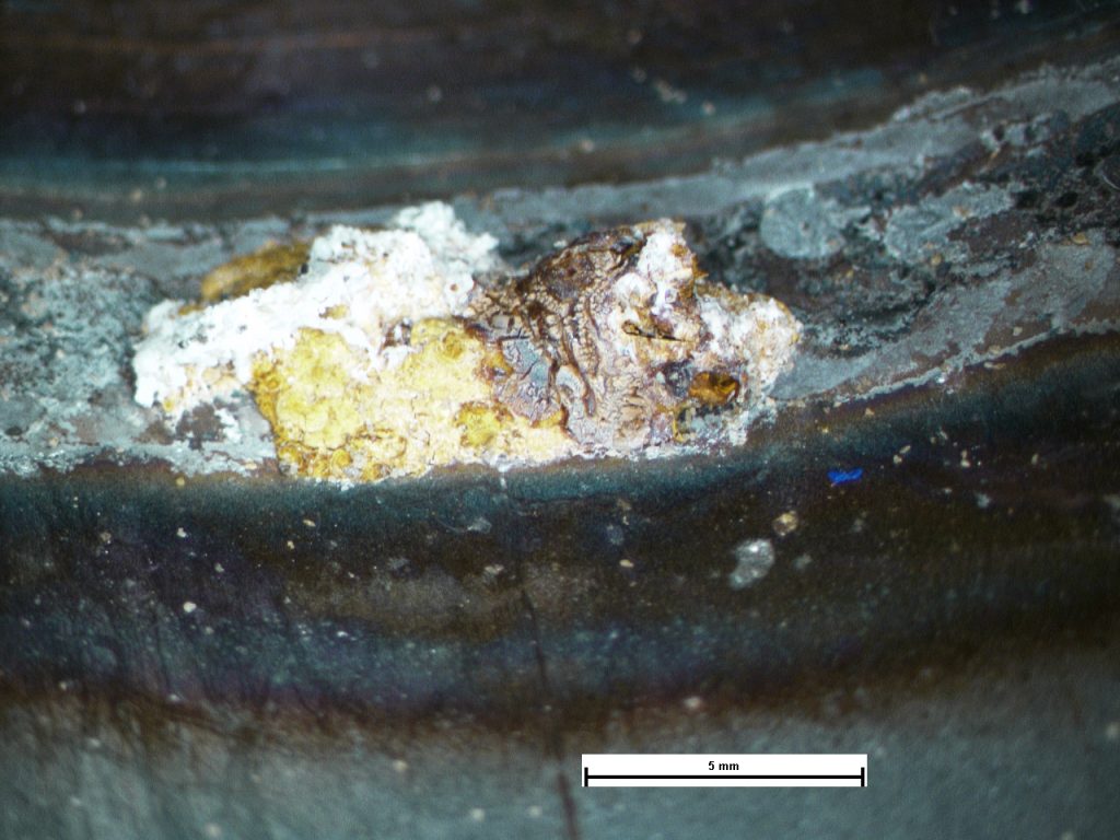


Corrosion pustule on the weld root.
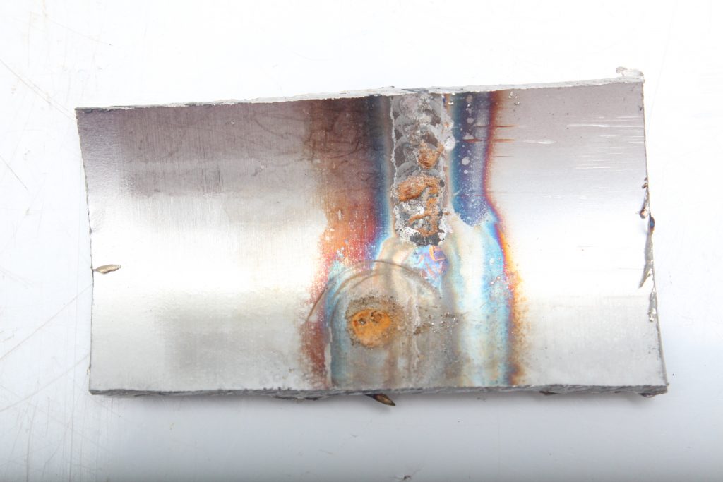


Section of the pipe at a weld showing high degree of oxidation (heat tint) from welding in an atmosphere rich in oxygen.
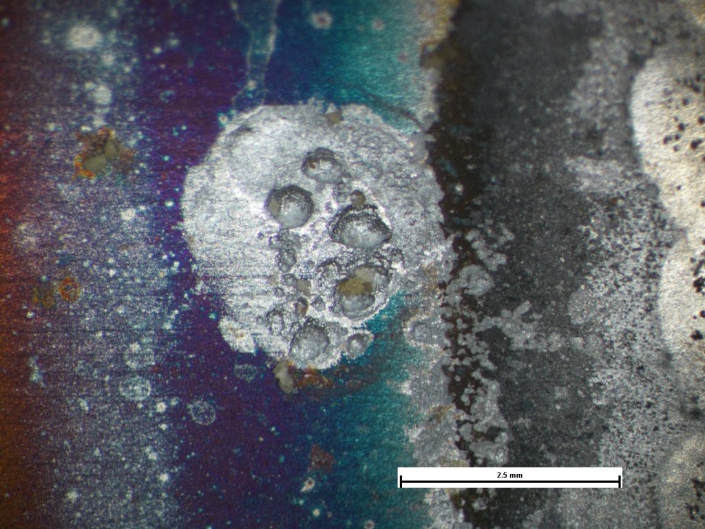


Area of severe pitting associated with heavy oxidation from the weld (far right).
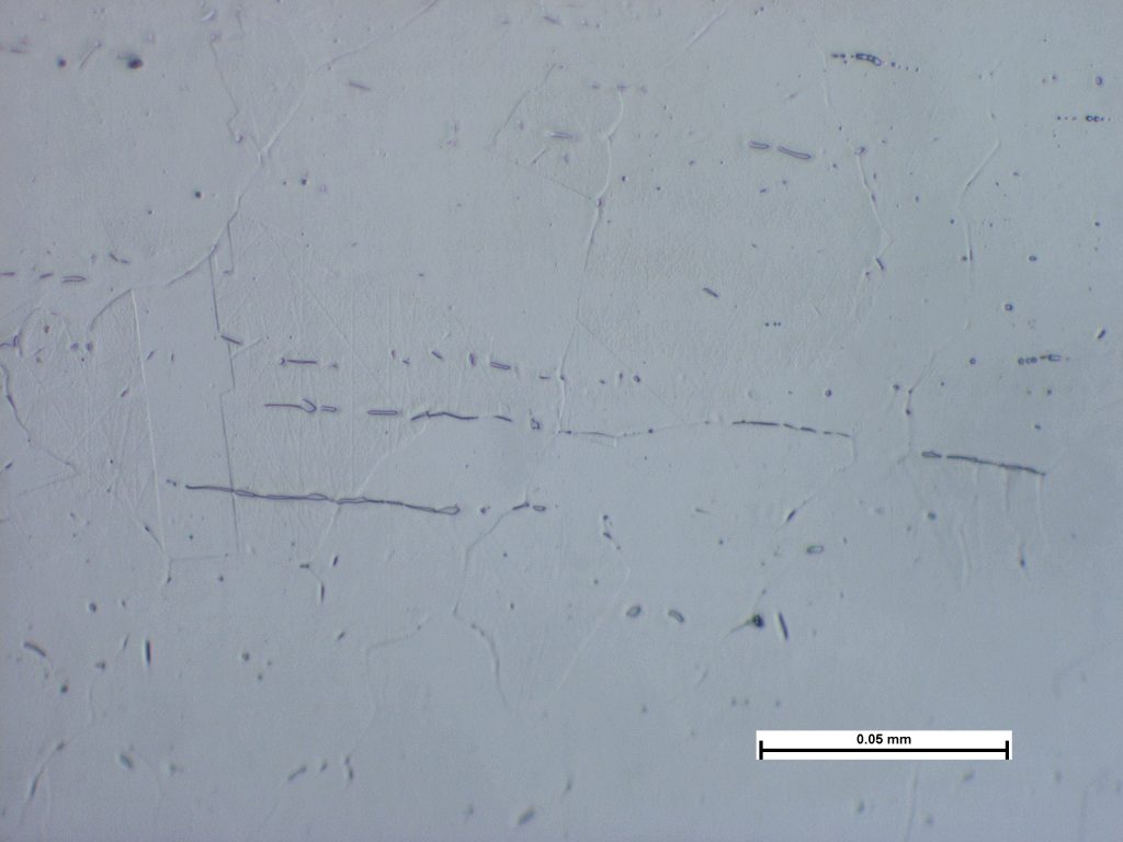


Photomicrograph of section through the HAZ of a pipe showing elongated pools of delta ferrite in an austenitic matrix. Sample etched in oxalic acid. Image taken at X500 Mag.
316L Process Pipe Corrosion
Three weeks after installation, 316L pipework started to leak from pinhole defects. These were predominantly located at welds that exhibited high temperature oxidation (heat tints) at the heat affected zones. Those welds that did not exhibit such oxidation were unaffected. Corrosion pustules were observed at the sites of the leaks and pitting corrosion had developed beneath the pustules. The pustules and pits exhibited characteristics that were indicative of a microbially influenced corrosion (MIC) mechanism. It would seem plausible that microbial activity was introduced when the system was flushed with water that had been held for prolonged periods in storage tanks. Use of biocides had not been considered. Apart from the heat tints, the quality of the welding was generally good with only minor areas of lack of root penetration, although these had neither caused nor contributed to the corrosion. The heat tints had contributed to the observed corrosion and it was recommended that welding procedures be reviewed to prevent such oxidation from occurring, or measures such as pickling and passivating the pipework post-welding to remove the tints, be undertaken. The materials analysed were consistent with a 316L grade of austenitic stainless steel and no evidence of deleterious material or microstructural effects was observed.
Fractured Welded Bracket
A fabricated bracket had fractured in service at one of the welds in a manner that was consistent with mechanical overload from be...
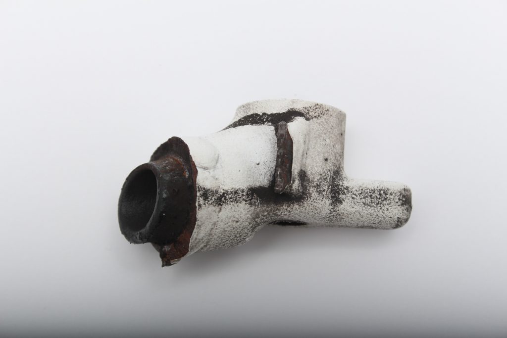


The bracket as received.
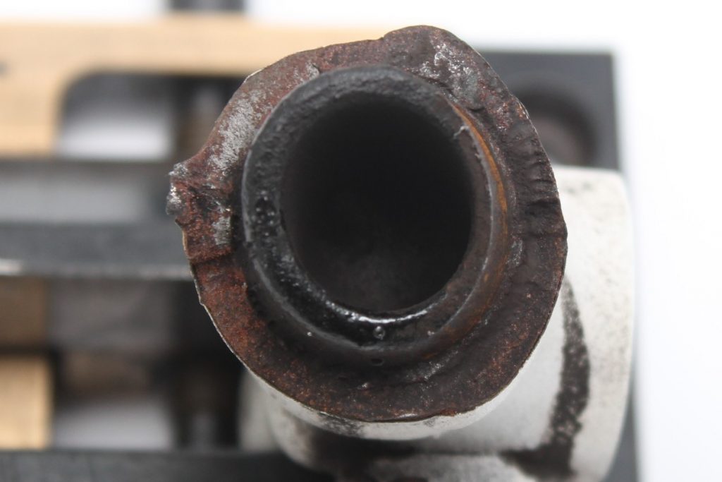


The fracture surface prior to acid cleaning (reference point arrowed).
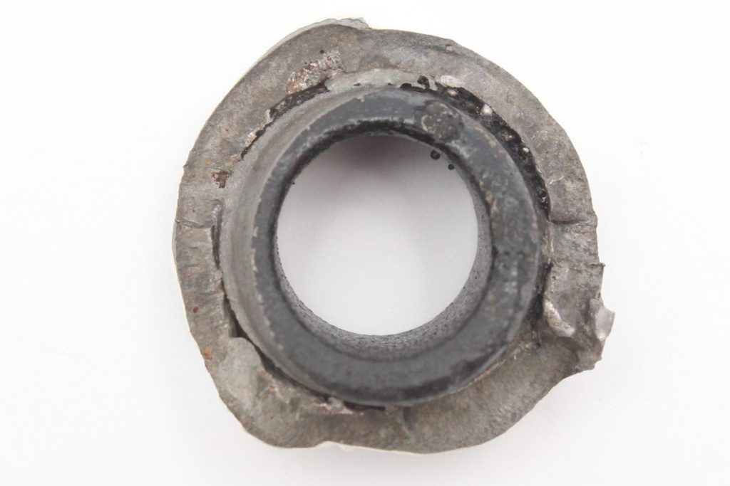


Plan view of the cleaned fracture surface.
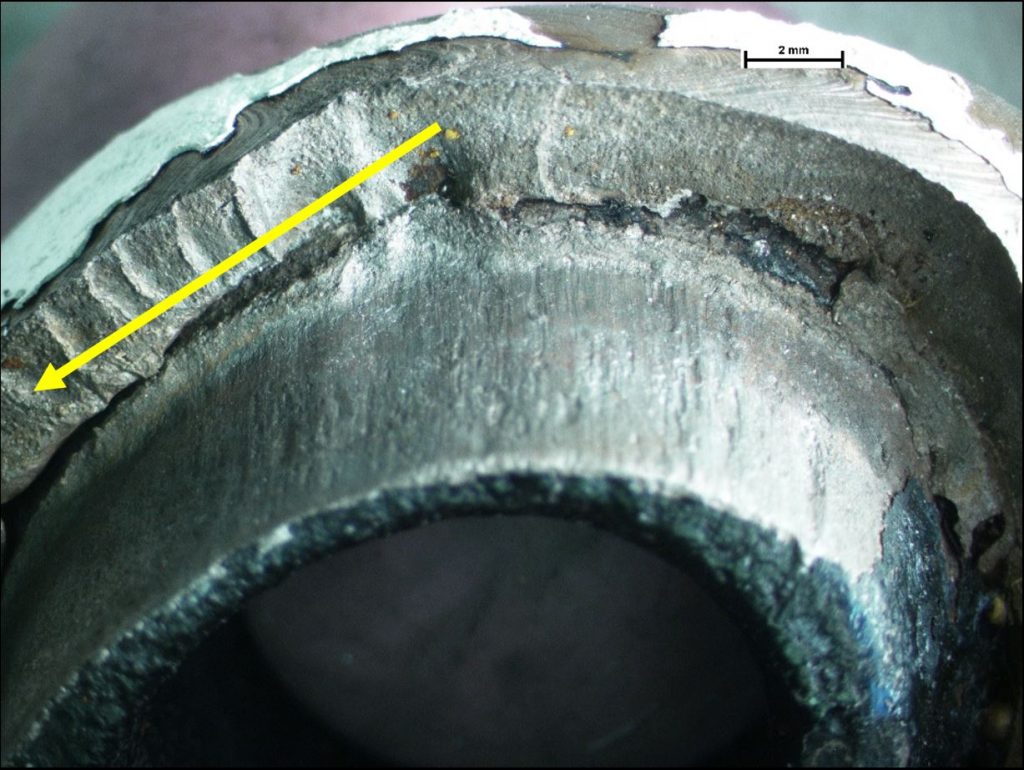


Portion of the weld fracture displaying a stepped surface from crack propagation (direction of propagation arrowed) and linear score markings on the spigot surface.
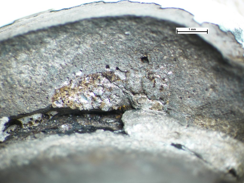


Magnified view of a portion of the weld fracture displaying lack of fusion, porosity, and shallow root penetration.
Fractured Welded Bracket
A fabricated bracket had fractured in service at one of the welds in a manner that was consistent with mechanical overload from bending. The joint consisted of a tube being inserted over a spigot section of a casting, with a circumferential weld being applied. Poor weld fusion and lack of root penetration was observed which would have reduced the mechanical strength of the joint, and this was the primary contributor to the failure. It was also noted that the insertion depth of the spigot into the tube was relatively short and this would have provided reduced support to the joint, increasing stress.
Gear with Fractured Teeth
A catastrophic gear fracture had occurred in service. Four intact sections of gear teeth were retrieved from the gearbox and th...
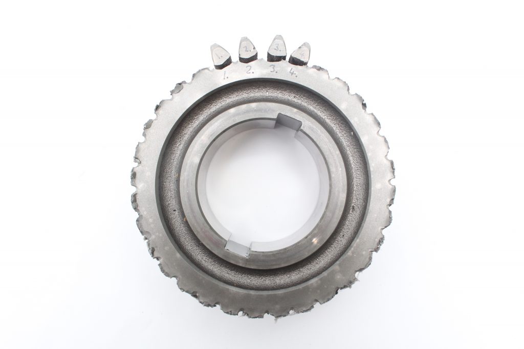


The gear as received with the remaining teeth.
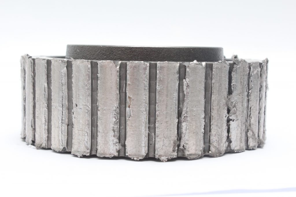


Heavily battered and smeared remnants of the gear teeth.
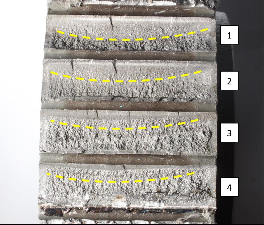


The four intact fracture faces numbered. Dashed line indicates nominal extent of staged fracture.
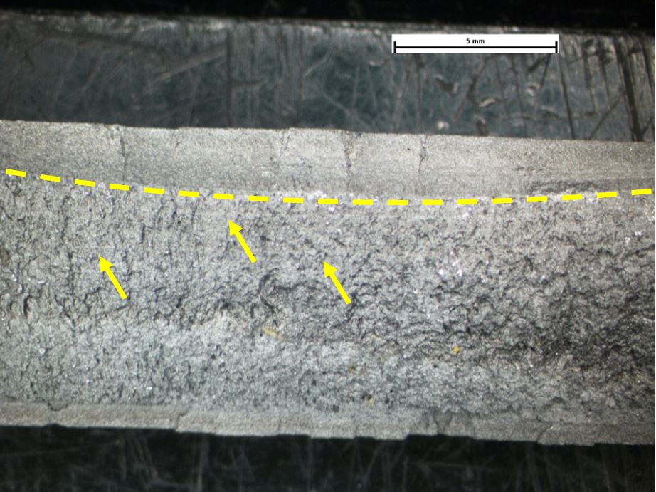


Tooth 3 revealing fatigue of the case (dashed line) and linear markings in the core (arrowed) consistent with staged fracture.
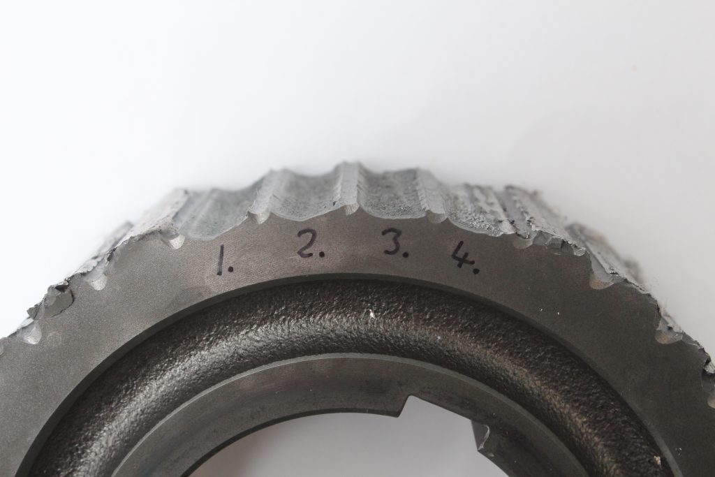


Variations observed in the tooth fracture cross-sections.
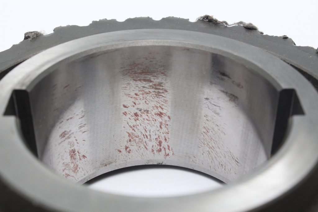


Bands of fretting wear in the gear bore.
Gear with Fractured Teeth
A catastrophic gear fracture had occurred in service. Four intact sections of gear teeth were retrieved from the gearbox and these matched with four consecutive intact fracture faces on the gear. The remaining gear teeth had been destroyed resulting in severe battering and smear of the surfaces, leaving a short protruding section of material. A fractographic assessment was conducted on the four teeth which revealed an outer circumferential band of fine-grained material and a coarse core material; features consistent with case hardening. At the fillet radius of the driven face, concentric markings typical of fatigue could be observed on all four fractures i.e. they were not overloaded in a single loading event. The bore of the gear revealed longitudinal bands of fretting wear indicative of movement in service for a prolonged period of time. The gear had failed due to the fracturing and detachment of the four teeth, which led to shearing and battering of the remaining teeth. Examination of the detached teeth surfaces revealed a variation in the extent of wear damage on the surfaces indicating the teeth detached in a staged manner i.e. the teeth with the least damage initially fractured, which resulted in subsequent meshing issues with the adjacent teeth, accelerating the degradation. No signs of misalignment were observed on the detached teeth.
Forging with a Crack Identified after the Heat Treatment Processes
Following final heat treatment, magnetic particle inspection of forgings identified areas of craze cracks, that were associated wi...
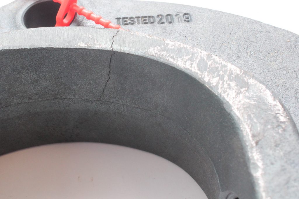


Detail of the crack location.
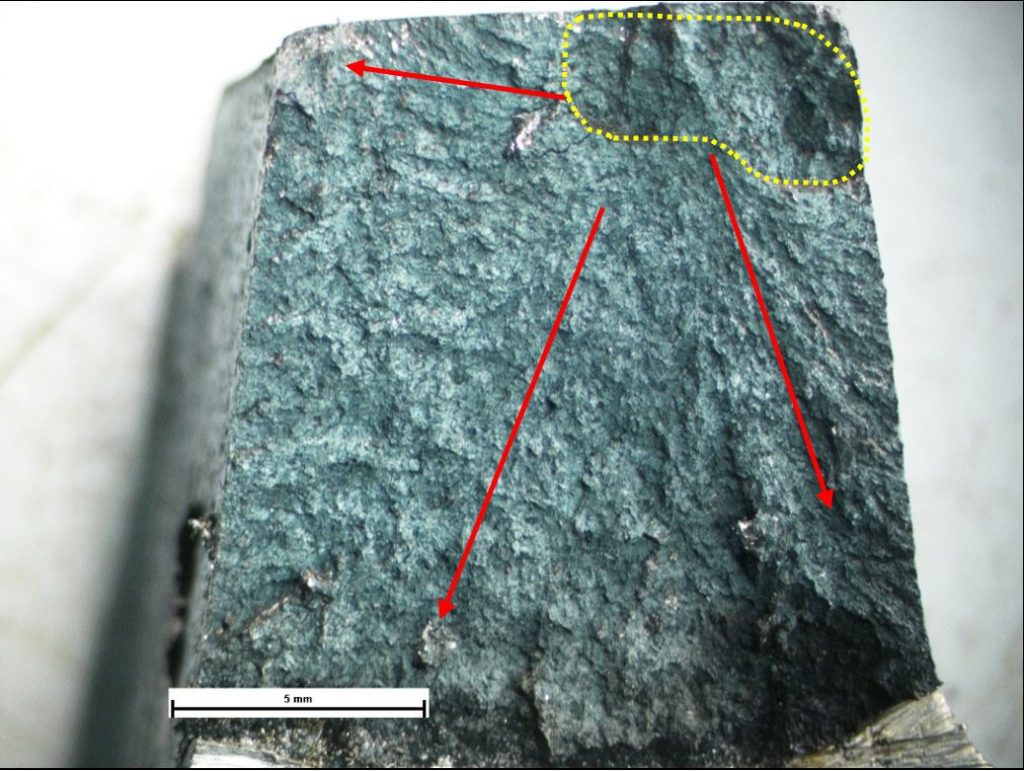


Fracture face of main crack showing heavy and even high temperature oxidation. General crack propagation direction shown by arrows, and area of initiation highlighted.
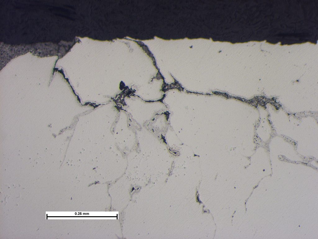


Photomicrograph of section through the lightly ground ‘crazed’ surface showing heavily oxidized lap-like features. Sample in the polished condition. Image taken at X100 Mag.
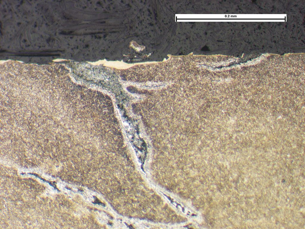


Photomicrograph showing lap defects, oxides, and decarburisation. Sample etched in 2% nitric acid in alcohol. Image taken at X200 Mag.
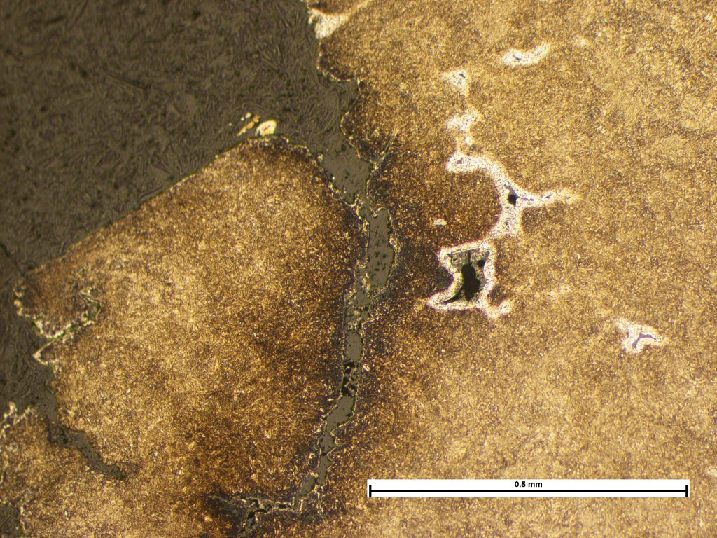


Photomicrograph of section through the main crack showing heavy decarburisation of lap/void defects and lighter decarburization of main fracture face. Sample etched in 2% Nital. Image taken at X100 Mag.
Forging with a Crack Identified after the Heat Treatment Processes
Following final heat treatment, magnetic particle inspection of forgings identified areas of craze cracks, that were associated with oxide-filled voids and lap defects. These subsurface defects were highly branched, heavily decarburised and oxidised, in a form that was consistent with forging laps. The main crack exhibited markedly different features consisting of brittle fracture, with lighter oxidation and decarburisation, compared to the forging laps or the outer surface. This main crack had also initiated in one of the areas of laps, and crack opening indicated relief of stress, possibly originating from residual stress developed from effects such as forging, quenching, or other thermal gradients (e.g. such as from rapid heating). Decarburisation typically occurs at temperatures in excess of approximately 700°C which indicated that the laps and main crack were present when exposed to such temperatures and the varying levels of decarburisation suggested that the main crack had been present for a shorter period than the laps. It was reported that forging was carried out at 1260°C followed by a sub-critical anneal at 680°C and these temperatures would clearly be expected to cause the observed decarburisation and the oxidation; tempering temperatures would not be sufficiently high to cause the decarburisation and oxidation observed. So, from the available information, the main crack had occurred or had been present during the forging and annealing stages.
Corrosion Fatigue of Screws
Zinc plated flanged screws used to secure a subsea pump housing had fractured in service. The screws were identified on the head ...


Fracture surface showing main directions of crack propagation.
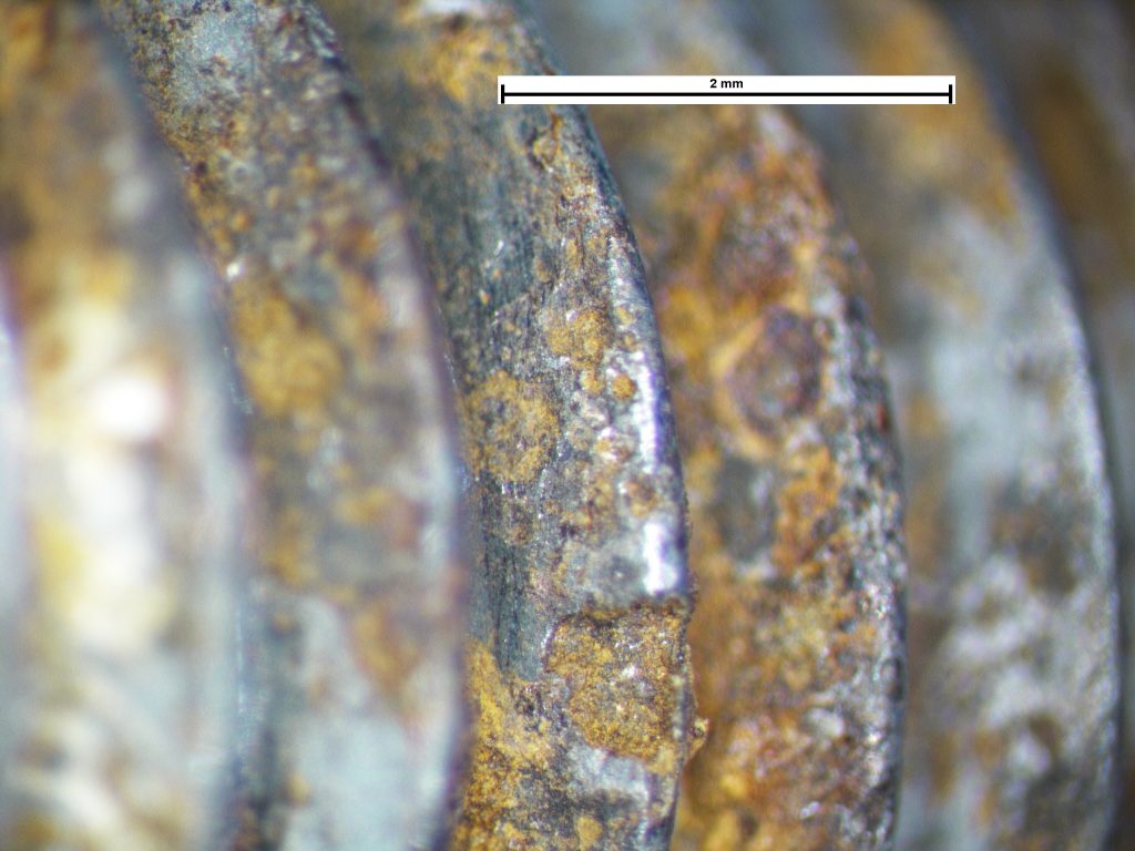


Corrosion pits on the thread surfaces.
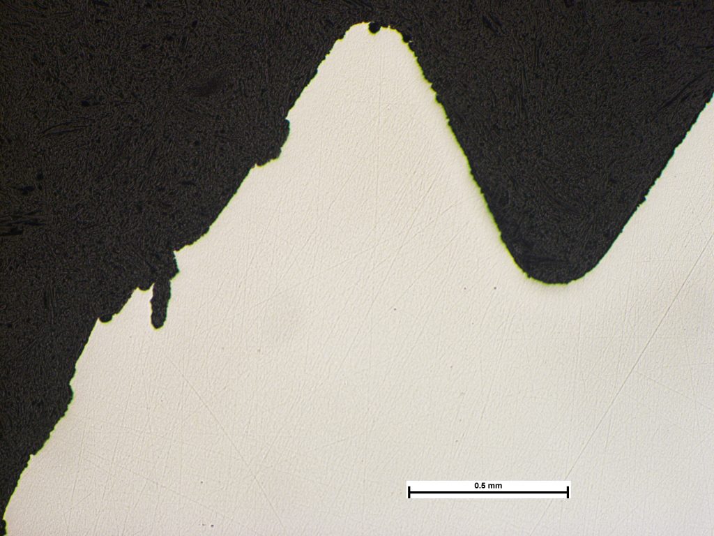


Photomicrograph of section through a location of fracture initiation showing corrosion pits on the thread and fracture surfaces. Sample polished. Image taken at X50
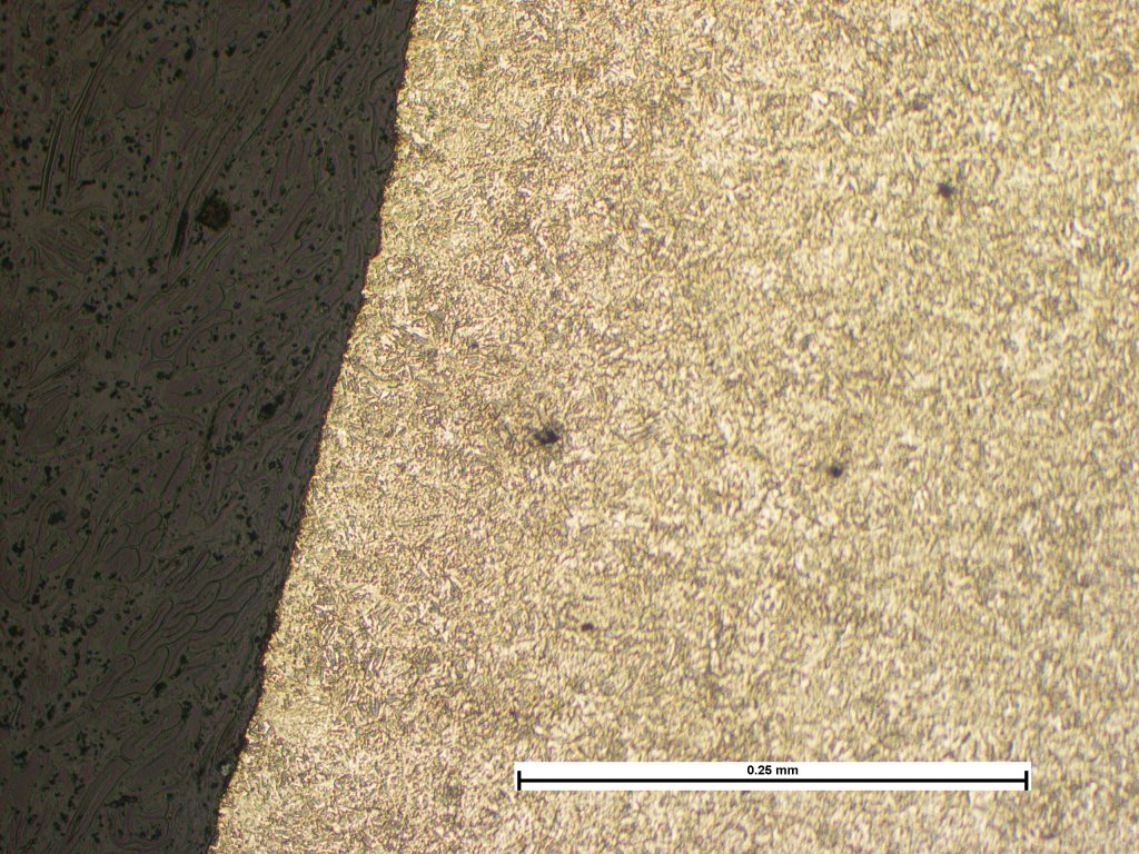


Photomicrograph of section through fracture face showing straight and transgranular mode of propagation typical of fatigue crack growth. Microstructure consists of tempered martensite. Sample etched in 2% nitric acid in alcohol. Image taken at X200 Mag.
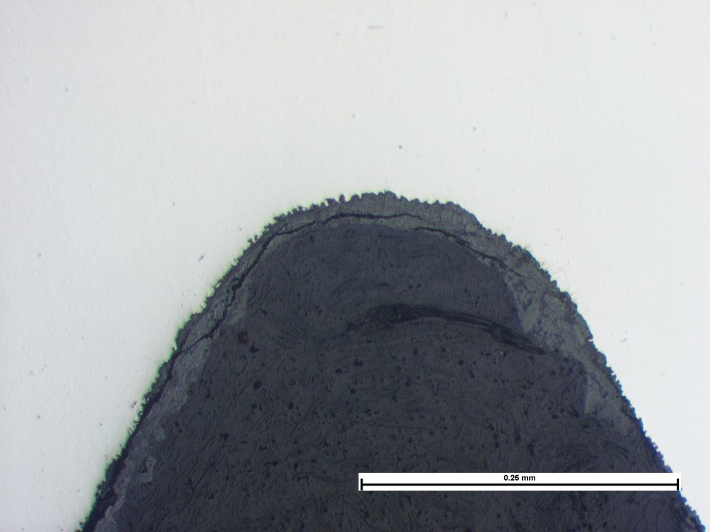


Photomicrograph of section through a thread root on an intact screw showing corrosion attack of the surface. Sample as polished. Image taken at X200 Mag.
Corrosion Fatigue of Screws
Zinc plated flanged screws used to secure a subsea pump housing had fractured in service. The screws were identified on the head as being ISO898-1 grade12.9. Hardness testing results conformed to the specification. Examination of the thread surfaces revealed heavy pitting consistent with in-service corrosion and general surface corrosion was present on the fracture face. The fracture was relatively flat and had multiple ‘thumbnail’ features around the circumference with concentric markings indicative of fatigue, with loading in multiple axes. Metallographic examination revealed directional pitting in the vicinity of the fracture and a crack propagation consistent with fatigue. It was concluded that the screws failed by a progressive crack mechanism assisted by corrosion.
Tube that had Fractured During a Routine Bending Operation
Initial examination indicated that the tube material had failed in a ductile manner with crack initiation expected to have occurre...
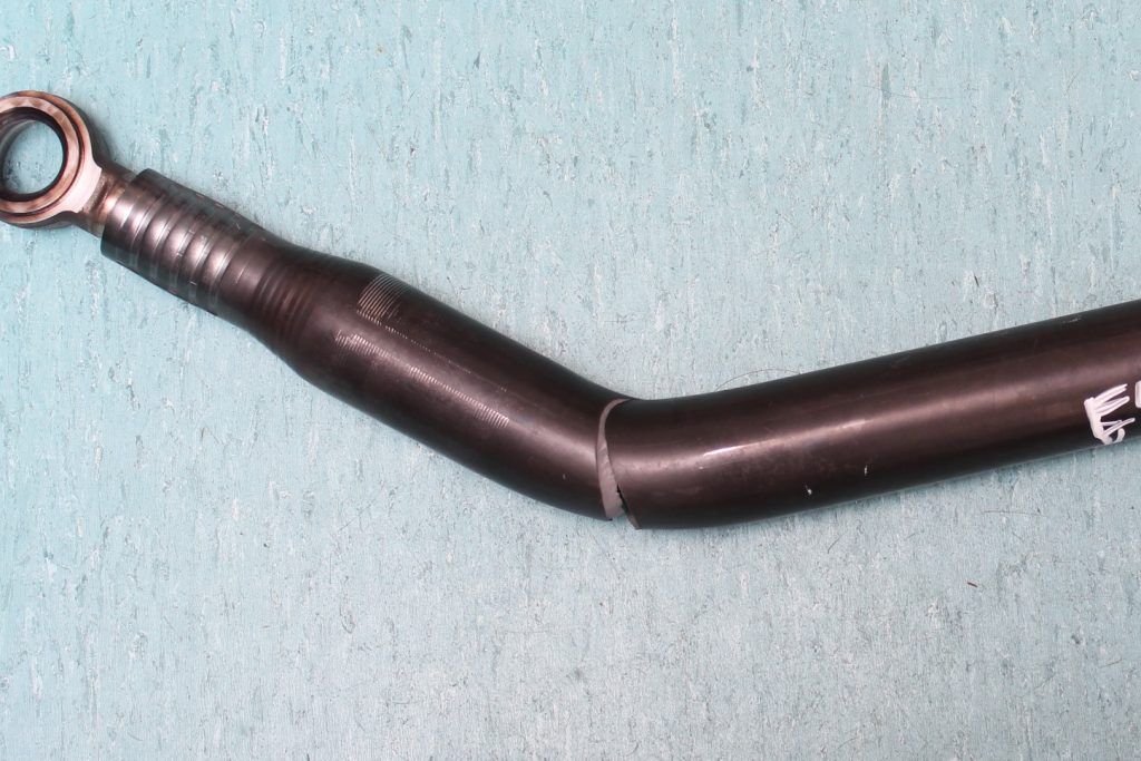


The tube as received.
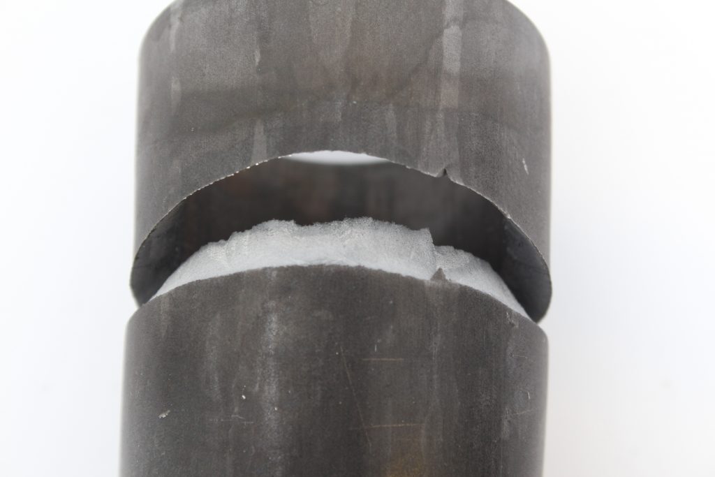


Opening of the crack on the extrados.
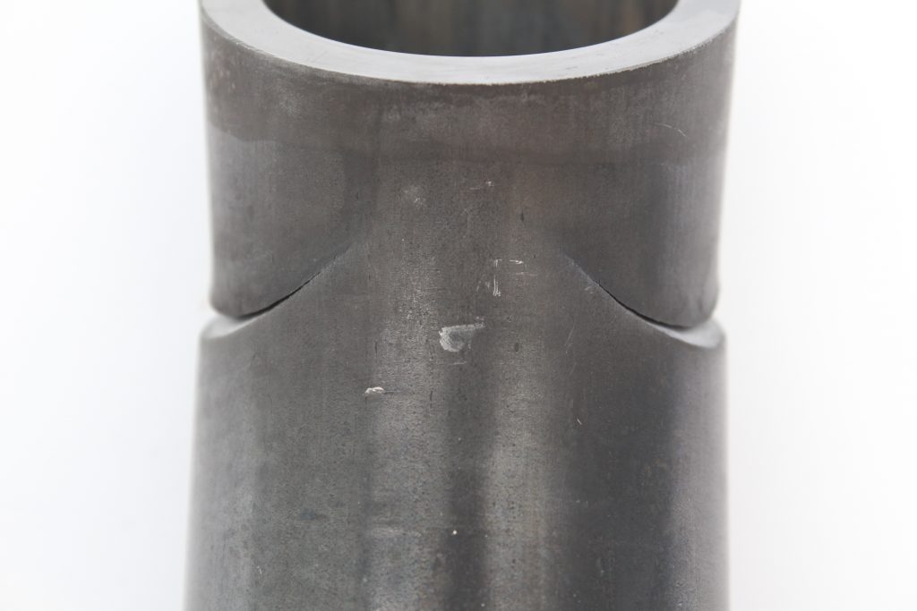


Intrados displaying the remaining ligament of material.
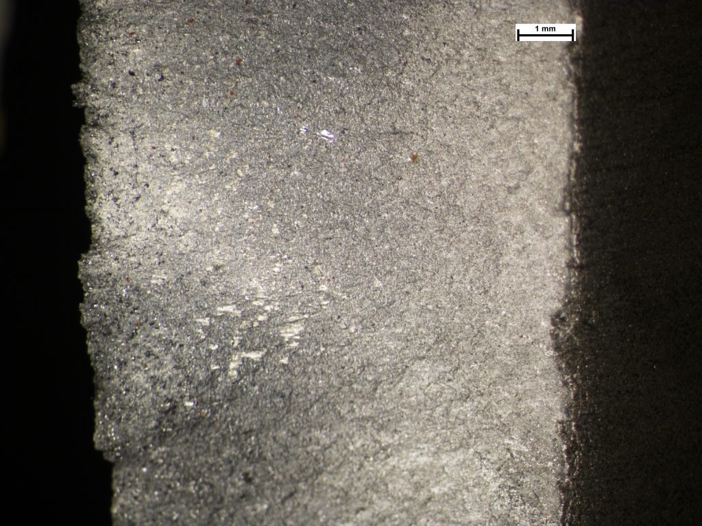


The initiation portion of the crack displaying a fracture surface consistent with ductile overload.


Transverse/circumferential cracking seen on the internal surfaces of the tube.


Microstructure away from the crack displaying a banded structure of ferrite and pearlite.


Photomicrograph displaying cracking adjacent to the main crack, located within the surface band of pearlite. Image taken at X100.
Tube that had Fractured During a Routine Bending Operation
Initial examination indicated that the tube material had failed in a ductile manner with crack initiation expected to have occurred on the outer surface. However, on the inner surface of the tube, adjacent to the main crack, smaller secondary cracks could be seen to have opened. Metallurgical examination revealed that the inner surface of the tube exhibited a change in microstructure from the remaining cross-section of material. The core structure consisted of ferrite and pearlite indicative of a medium carbon steel, whereas, the inner surface of the tube consisted of a fully pearlitic structure with grain boundary cementite indicative of a high carbon composition. This surface band would have exhibited markedly different mechanical properties, with an increase in hardness and reduction in toughness. On bending the tube, this pearlitic surface band had cracked in a brittle manner due to its inherent lack of ductility compared to the bulk of the tube material, with one such crack propagating through the full tube thickness. On investigation, at heat treatment during manufacture of the tube, lubricating oil remaining on the inner surface of the tube had led to diffusion of carbon into the surface, causing the change in microstructure.
Cracked Bearing Inner Sleeve
The inner race of a needle roller bearing used in a suspension linkage had fractured in service. Hardness testing established the...
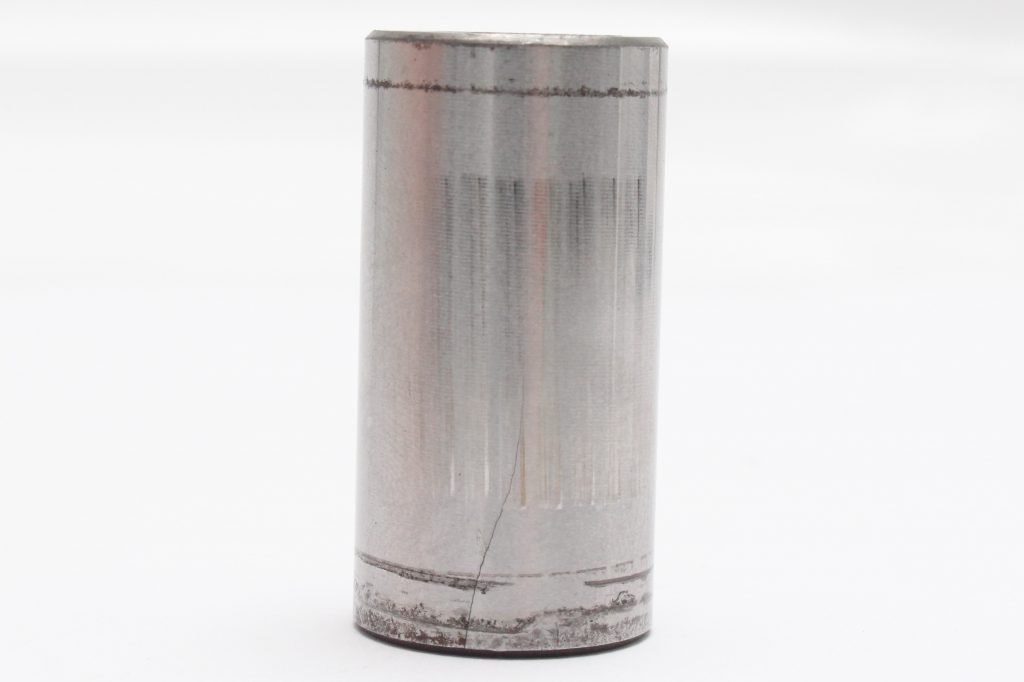


The fractured bearing race.
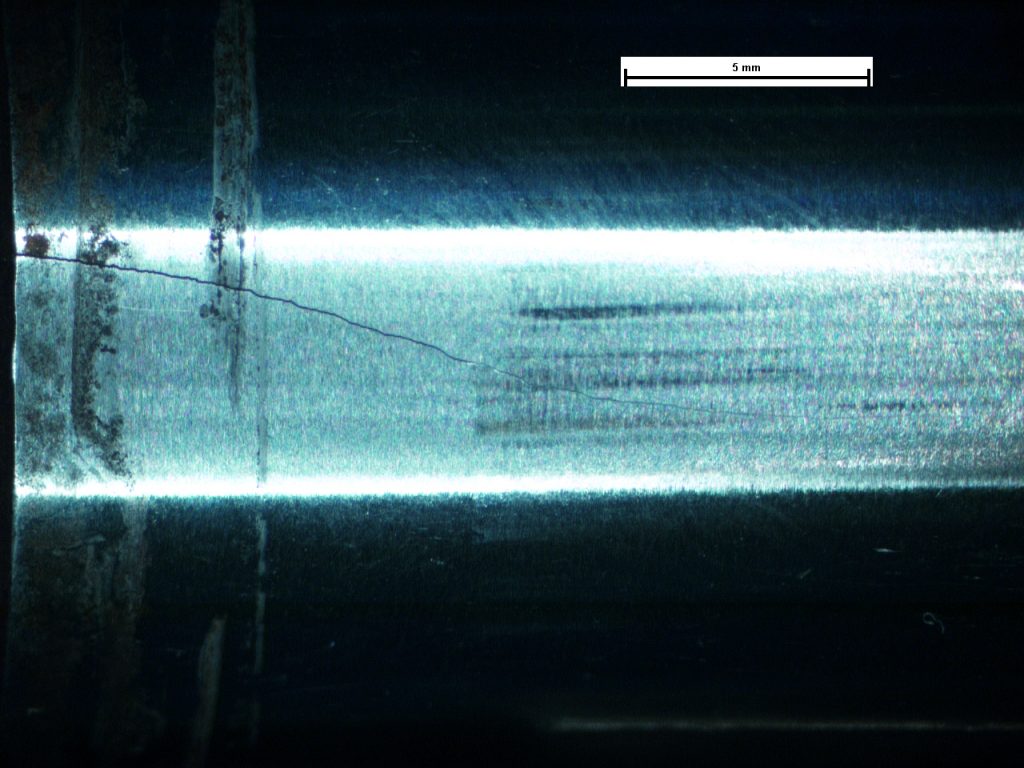


Plan image of the crack.


Bore surface with the central crack. Note poor machining quality.
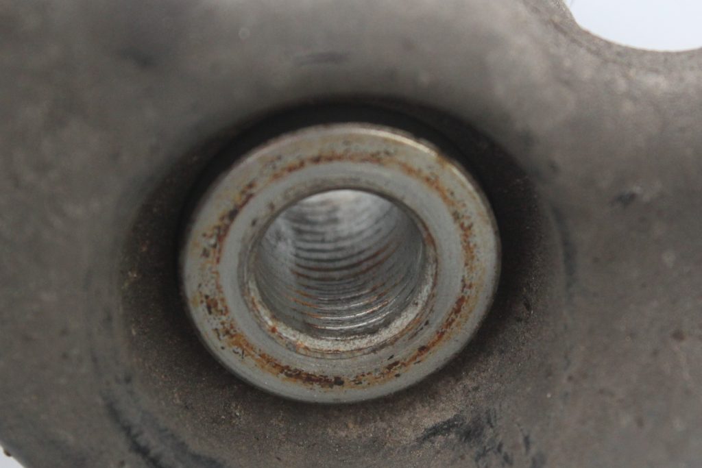


The inner race of the bearing showing thread impact damage.
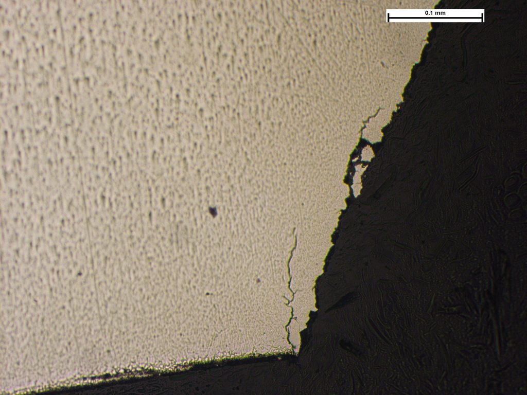


Section through the main crack face with multiple secondary cracks. Image taken at X200.
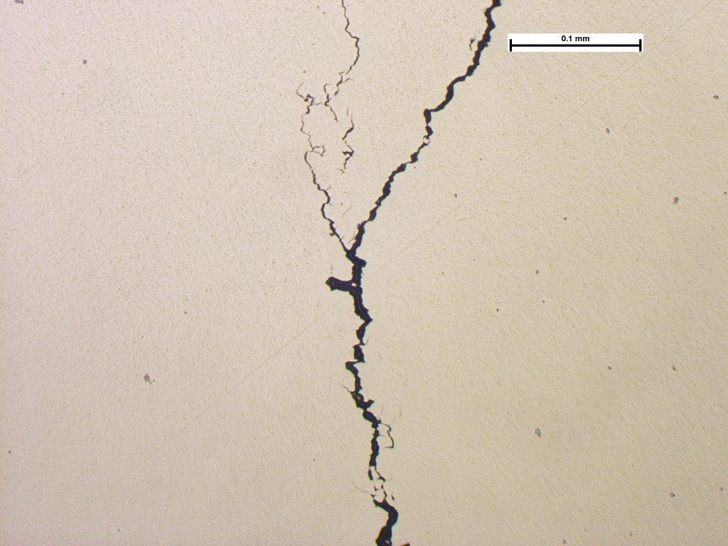


A further crack observed from the bore. Image taken at X200.
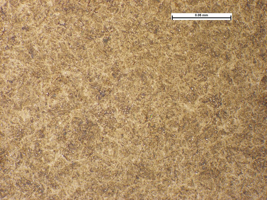


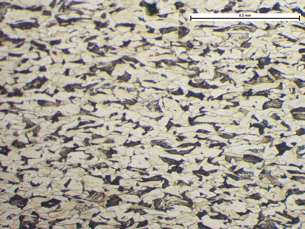
The core microstructure. Image taken at X500.
Cracked Bearing Inner Sleeve
The inner race of a needle roller bearing used in a suspension linkage had fractured in service. Hardness testing established the race was through-hardened and had a hardness that conformed to the specification. The bearing was poorly installed, being mounted on a bolt with a significant part of the race being supported on the bolt threads. Examination revealed indentation marks from the threads on one side of the bearing bore that indicated an occurrence of impact loading. The bore of the race was also poorly machined, with a surface typical of just being drilled with no other finishing as would be expected for a bearing. Witness marks on the rolling face of the race, from contact with the needle rollers, was observed on one quarter of its circumference. These marks comprised light wear marks in discrete locations, caused by vibrations/oscillations being transmitted through the bearing consistent with its application in a suspension linkage. Metallurgical examination revealed that the material had fractured in a brittle manner with cracks having initiated on the inner surface of the bore. No evidence of progressive crack growth such as by fatigue, was observed, and the evidence suggested that the crack had occurred in a one-off loading event. The clearance between the bolt and the race was such that radial movement could occur, and this would increase the potential for impact loads between the bolt (shank or threads) and the race. The poorly supported inner race of the bearing would be subjected to concentrated loading that would then lead to poor stress distribution within the race, and increase the potential for distortion and the mode of cracking as observed. Little consequential damage to the area of cracking, such as preferential wear of the edges of the fracture from contact with the rolling elements was observed, indicating it occurred late in the service period.
Turbine Housing Fatigue
Cracking within a turbocharger turbine housing. Examination revealed a crack extending around the majority of the housing circum...
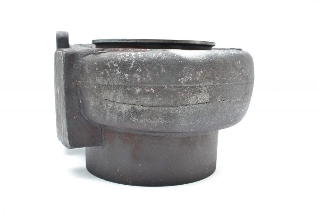


The turbine housing as received.
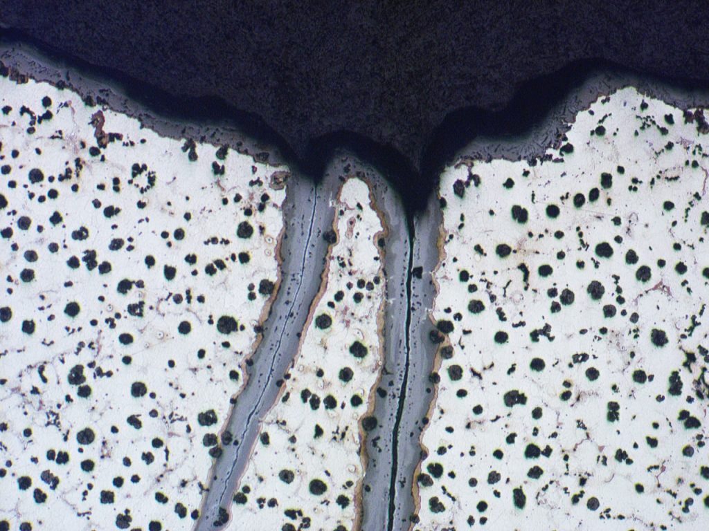


Thermal fatigue cracking. Heavy oxidation of crack surfaces. Image taken at X50.
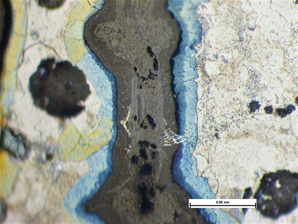


Crack surface oxidation with substantial material loss. Image taken at X500.
Turbine Housing Fatigue
Cracking within a turbocharger turbine housing. Examination revealed a crack extending around the majority of the housing circumference, located at a parting line. The crack was heavily oxidised; the degree of oxidation reduced with distance from the surface of initiation to the crack tips which indicated that cracking was progressive. Fracture was established to be caused by thermal fatigue, where fluctuating temperatures introduce cyclic stress.
Stress Corrosion Cracking of 316 Diaphragm Material
The failure of the diaphragm plate was established to be caused by stress corrosion cracking (SCC). The SCC was only associated w...
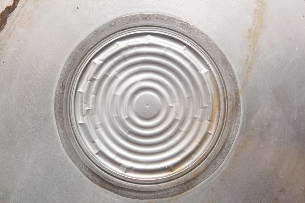


The diaphragm as received.
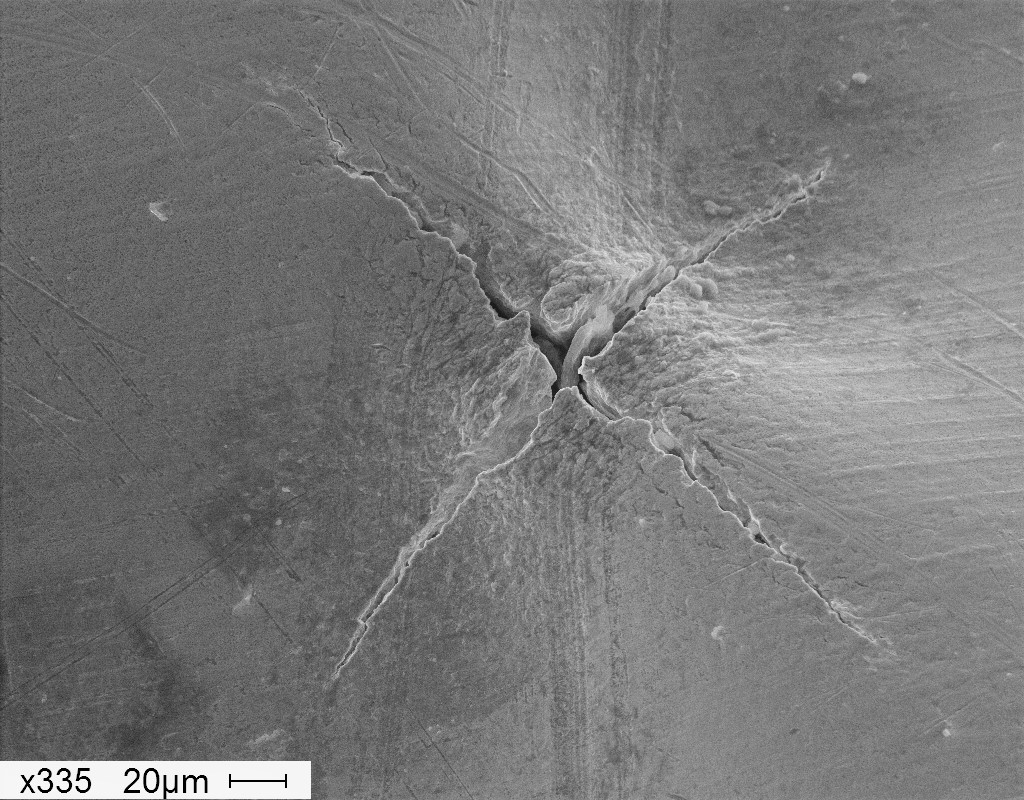


SEM examination of the cracks revealing a brittle fractures mode. Image taken at X335.
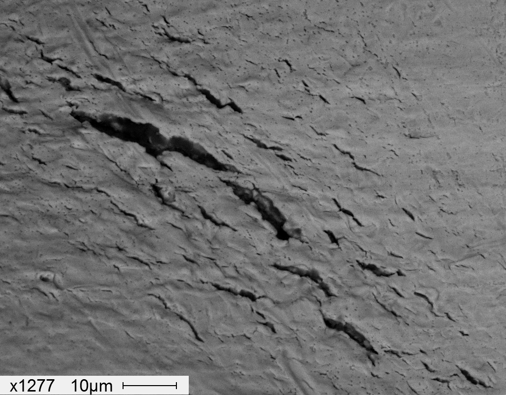


Multiple cracks observed consistent with stress corrosion cracking.
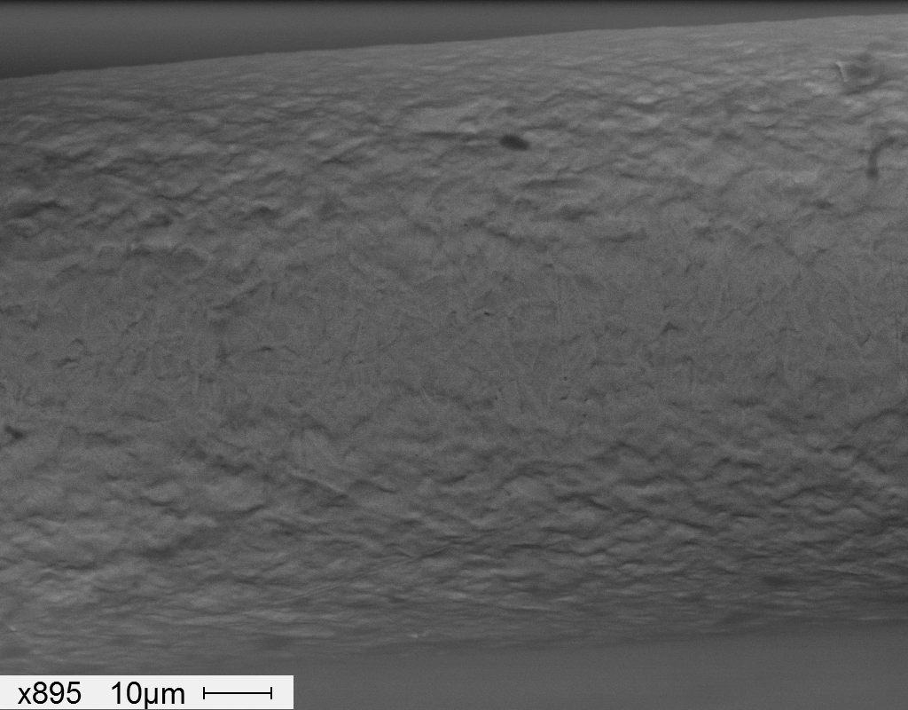


SEM image of the outer surface of a bend test carried out on a sample of material taken remote from the radial deformation ridges, revealing no cracking. This indicated that the material normally exhibited sufficient ductility.
Stress Corrosion Cracking of 316 Diaphragm Material
The failure of the diaphragm plate was established to be caused by stress corrosion cracking (SCC). The SCC was only associated with radially orientated ridges which were caused by an over-pressurisation event that plastically (permanently) deformed the diaphragm material. This had set up residual stress in the ridges and when exposed to regular cleaning with hydrochloric acid and the relatively aggressive process liquid, was sufficient to cause SCC. The remainder of the diaphragm remote from the radial deformation ridges was completely unaffected by SCC showing that the as manufactured material was adequate for the application under normal operating conditions.
Fractured Oil Pump Annulus
This annulus from an oil pump assembly fractured longitudinally at multiple locations. The fractures were brittle and exhibited c...


The sample as received.


An opened crack revealing concentric features which could be misinterpreted as beach marks of fatigue.


Macro etch of the cross section revealing the concentric bands to be inherent within the material.


Etched cross section revealing banding. Image taken at X50.
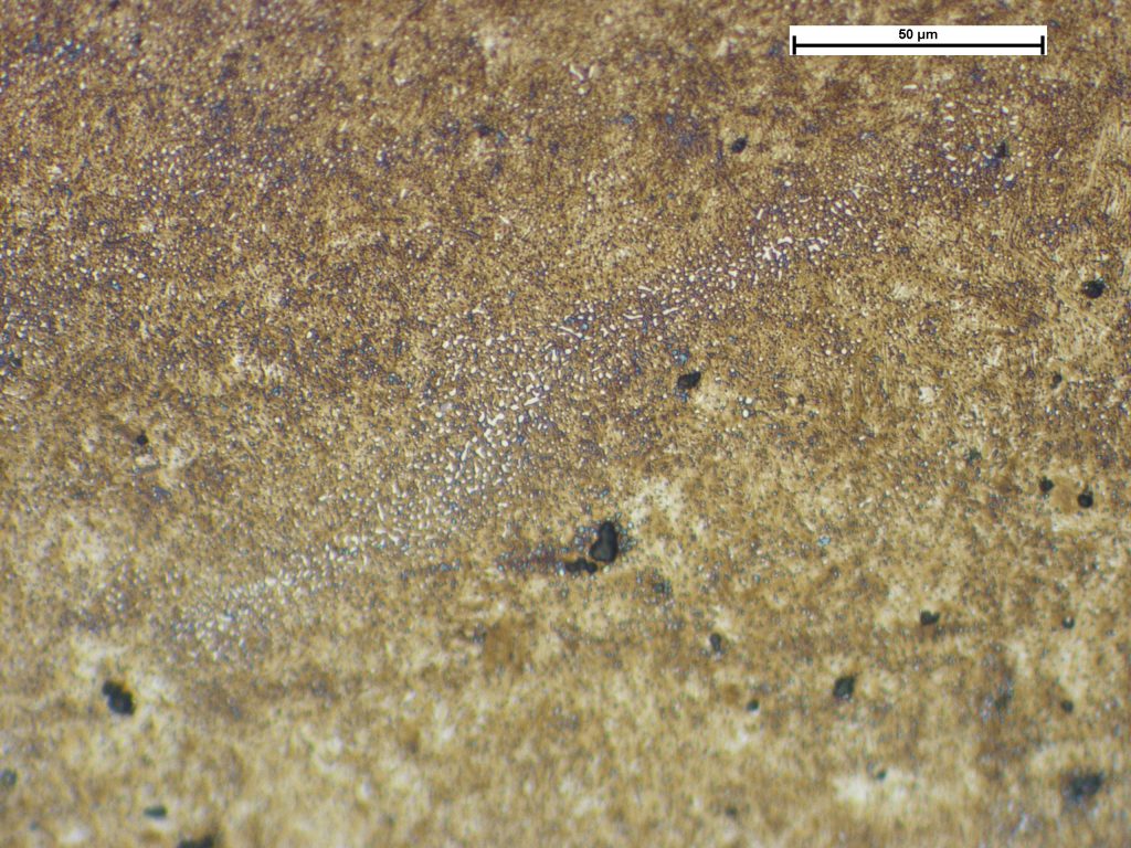


Higher magnification image revealing the bands to be consistent with carbides. Image taken at X500.
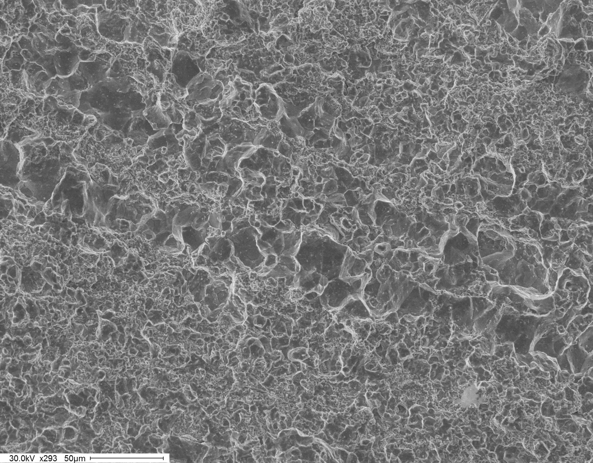


Bands of grain size variation observed on the fracture face. SEM Image taken at X293.
Fractured Oil Pump Annulus
This annulus from an oil pump assembly fractured longitudinally at multiple locations. The fractures were brittle and exhibited concentric ring features that radiated out from the middle of the inner surface. These could initially, and perhaps not unreasonably so, be identified as evidence of a progressive crack growth mechanism such as fatigue. However, more detailed examinations by optical and scanning electron microscopy revealed the concentric markings to be bands of inhomogeneity in the material, consisting of variations in the grain size and distribution of chromium carbides. Hardness testing revealed that these bands exhibited variations in hardness, and hence tensile properties. This variation may have increased the propensity to fracture although further examination of exemplar annuli that had provided service without failure was recommended to determine the relevance of the inhomogeneity to the current failure.
Fractured Cast Iron Bearing Insert
During production, the flake graphite cast iron bearing insert is positioned into a mould which is then filled with molten alumini...
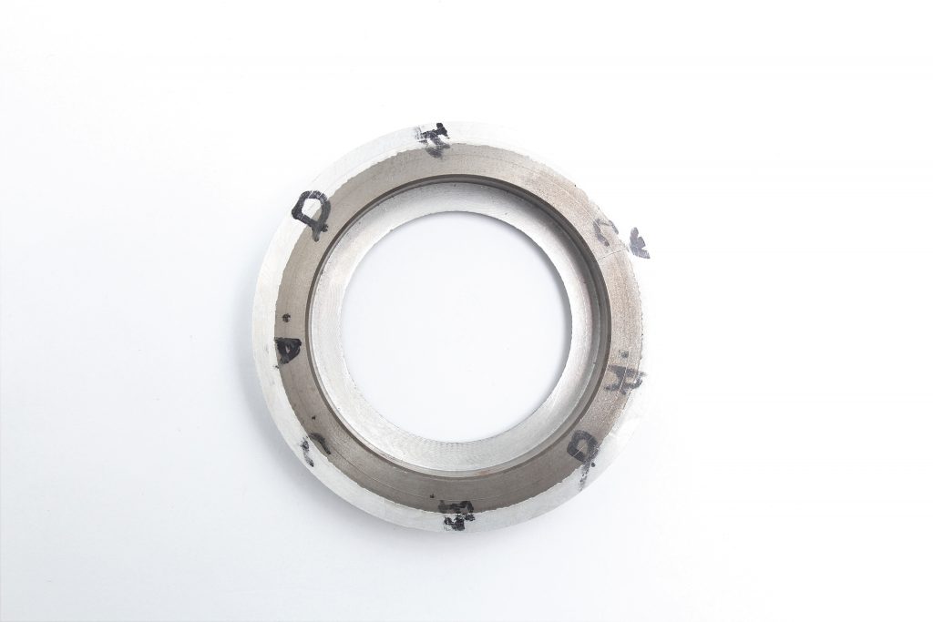


Cast iron bearing insert surrounded by a section of cast aluminium. The sample shown above had been machined from the main section of the aluminium casting for submission to the laboratory.
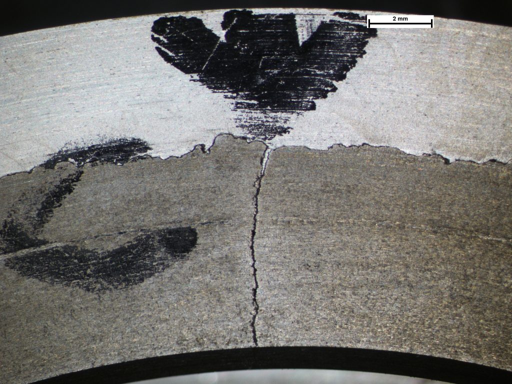


Crack. Ingress of aluminum shown in expanded image.
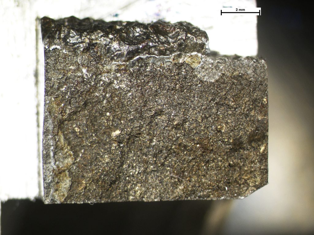


The brittle fracture surface.
Fractured Cast Iron Bearing Insert
During production, the flake graphite cast iron bearing insert is positioned into a mould which is then filled with molten aluminium. The insert was found to have fractured following a period in service. Ingress of aluminium into the crack was observed which revealed the bearing ring was either cracked before or during pouring of the aluminium, rather than during subsequent machining or whilst in service i.e. it was a manufacturing defect.
 Account

