Library of Failures
A library of classical material failure examples. Use the filter options to refine your search.
Motorcycle Fixing Component
Examination of a motocycle fixing component consisting of a formed strip of low carbon steel and Rivnut mountings. A great exten...
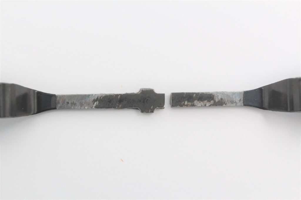


Wear markings on the ‘inside’ surface of the fixing.
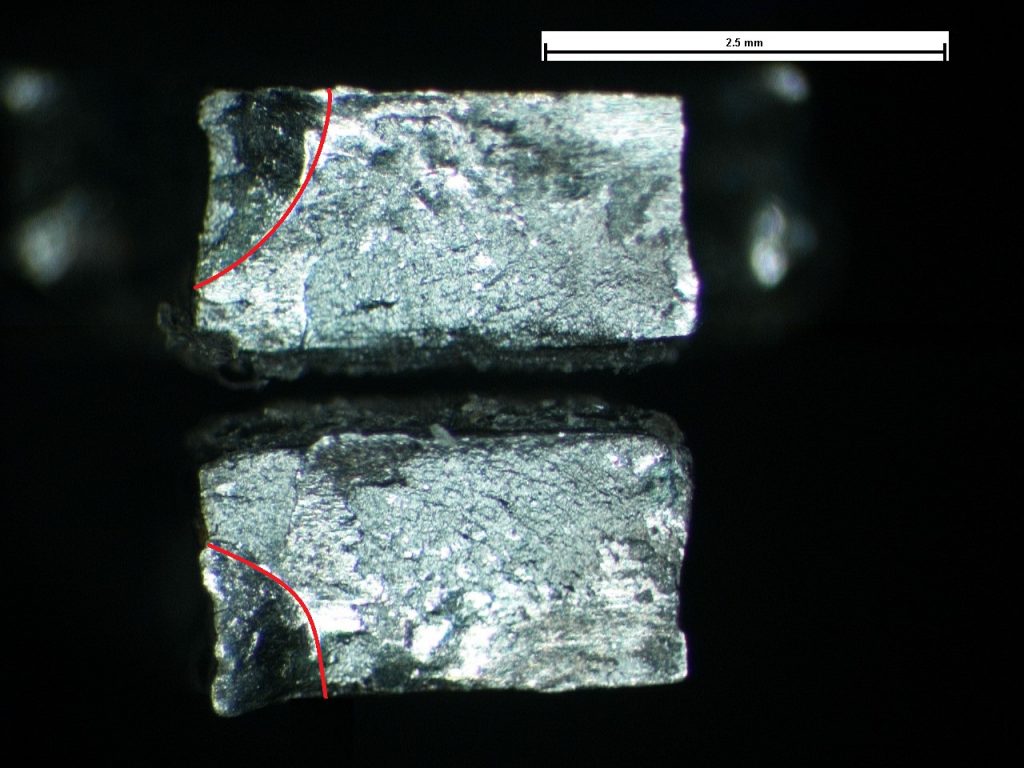


The fracture surfaces. 45° portion highlighted.
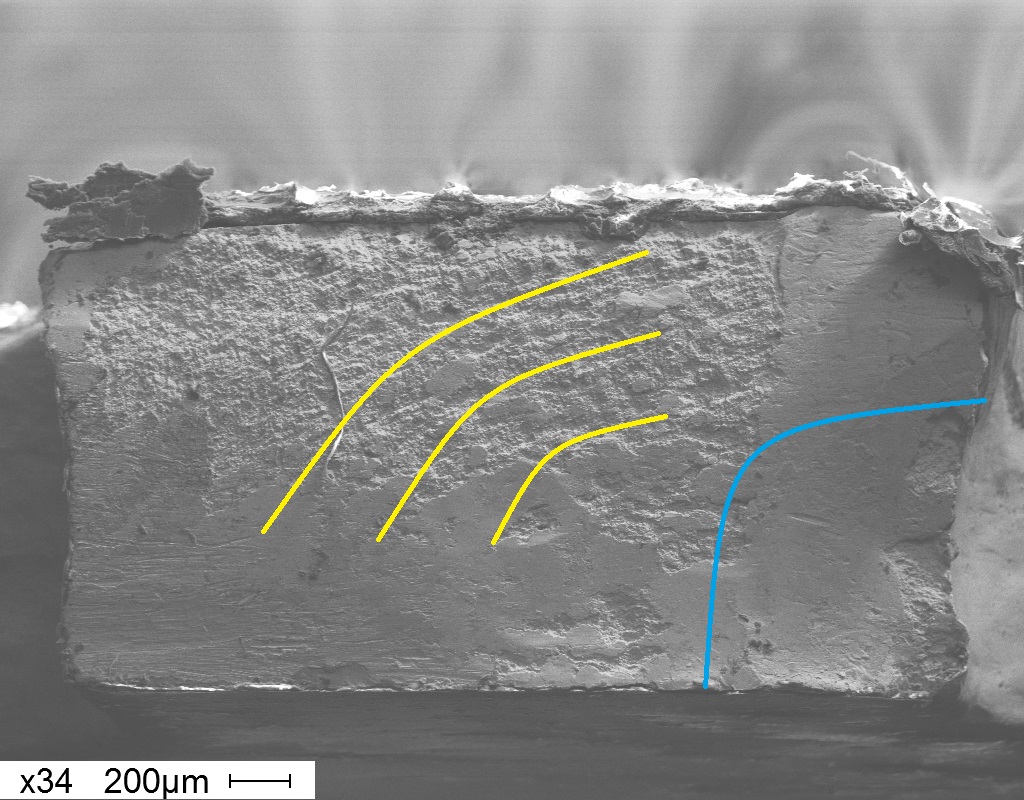


Plan SEM image of the fracture surface (concentric features highlighted in yellow, 45° portion of the fracture highlighted in blue). Image taken at X34.
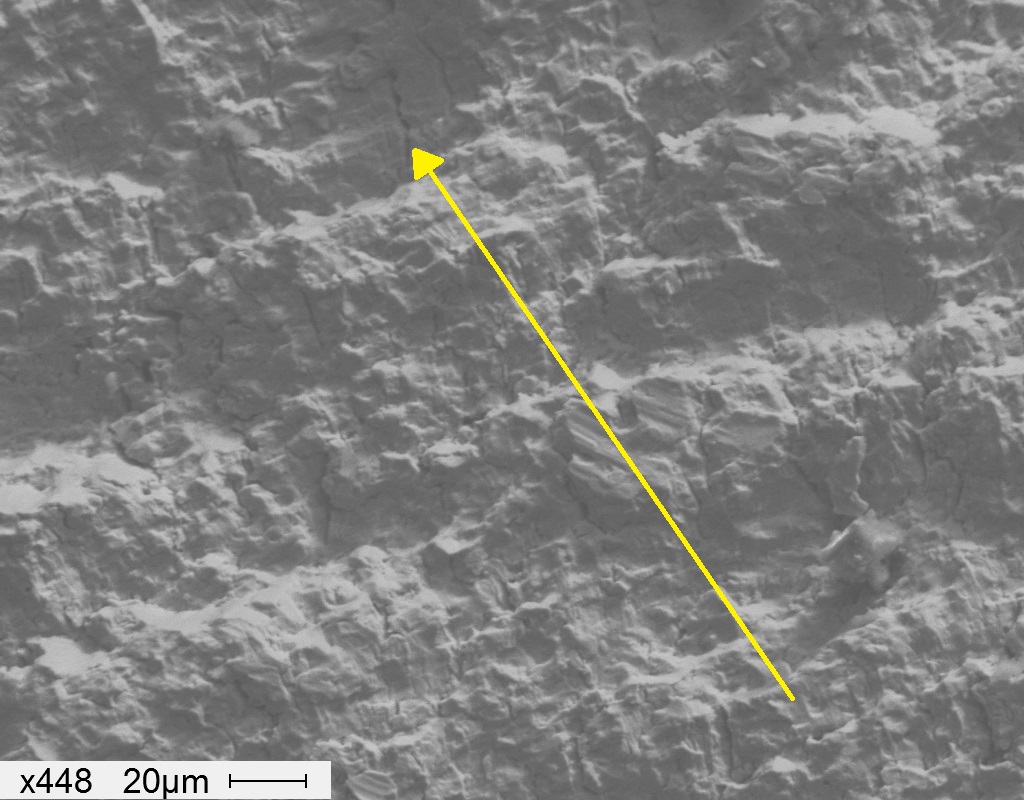


Direction of crack propagation highlighted. Image taken at X448.
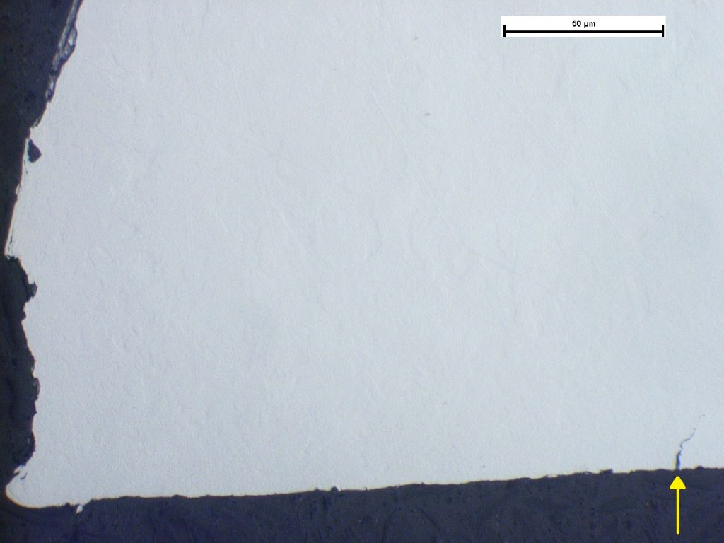


Secondary crack adjacent the main fracture highlighted. Image taken at X500.
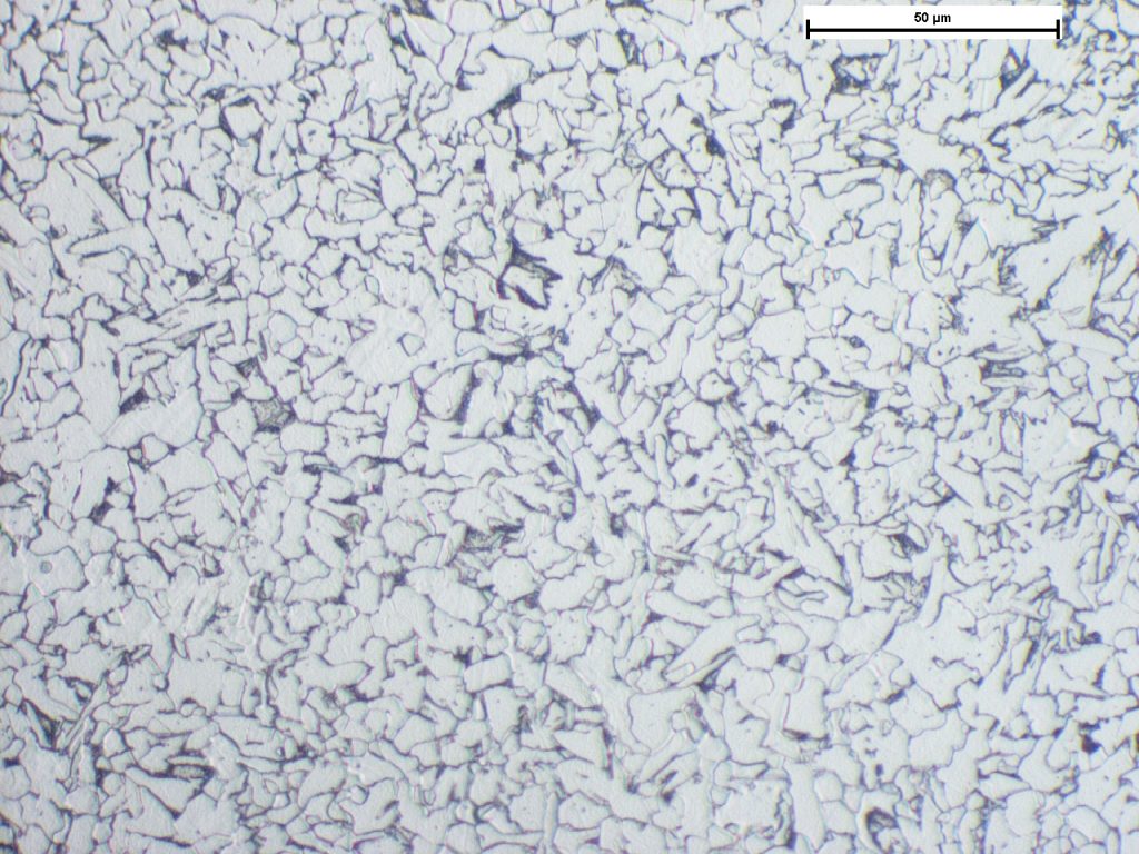


Photomicrograph of the microstructure. Image taken at X500.
Motorcycle Fixing Component
Examination of a motocycle fixing component consisting of a formed strip of low carbon steel and Rivnut mountings. A great extent of fretting and polishing was observed on the inside surface of a fixing bar as well as on the Rivnut faces consistent with movement in service. Rotational wear markings on the ‘left’ Rivnut indicated that the screws had been moving in service, possibly as a consequence of insufficient torque. The fracture face was heavily battered, and smearing damage in the area of initiation meant that that the initiation portion of the fracture could not be observed. The material either side of the fracture did not exhibit any degree of plastic deformation as would be expected if the material had fractured due to mechanical overload. The brittle nature of the crack, and the linear step features on the fracture face indicated that fracture was by a fatigue mechanism. When materials experience cyclic loading above their fatigue limit often multiple fatigue cracks nucleate. Over time, one crack in the area of highest load tends to relieve stress at the other cracks and become ‘dominant’ causing some of the initial cracks to be arrested. The secondary crack adjacent to the fracture was too small to be able to determine its fracture mode with certainty but given its relatively brittle fracture mode, was probably an embryonic secondary fatigue crack.
Environmental Stress Cracking of Injection Moulded Pegs
Cracking of ~2mm Dia. pegs used in conjunction with a self tapping screw to secure bearings to a injection moulded PC-ABS componen...
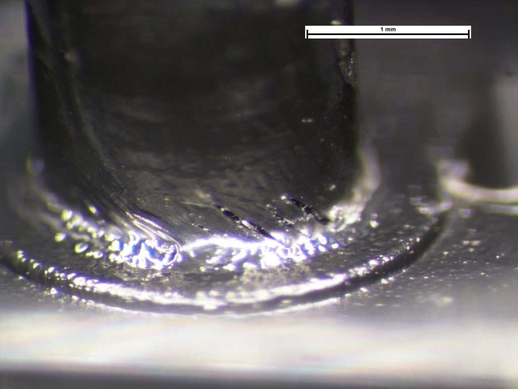


Multiple cracks in the peg radius. Sample from service.
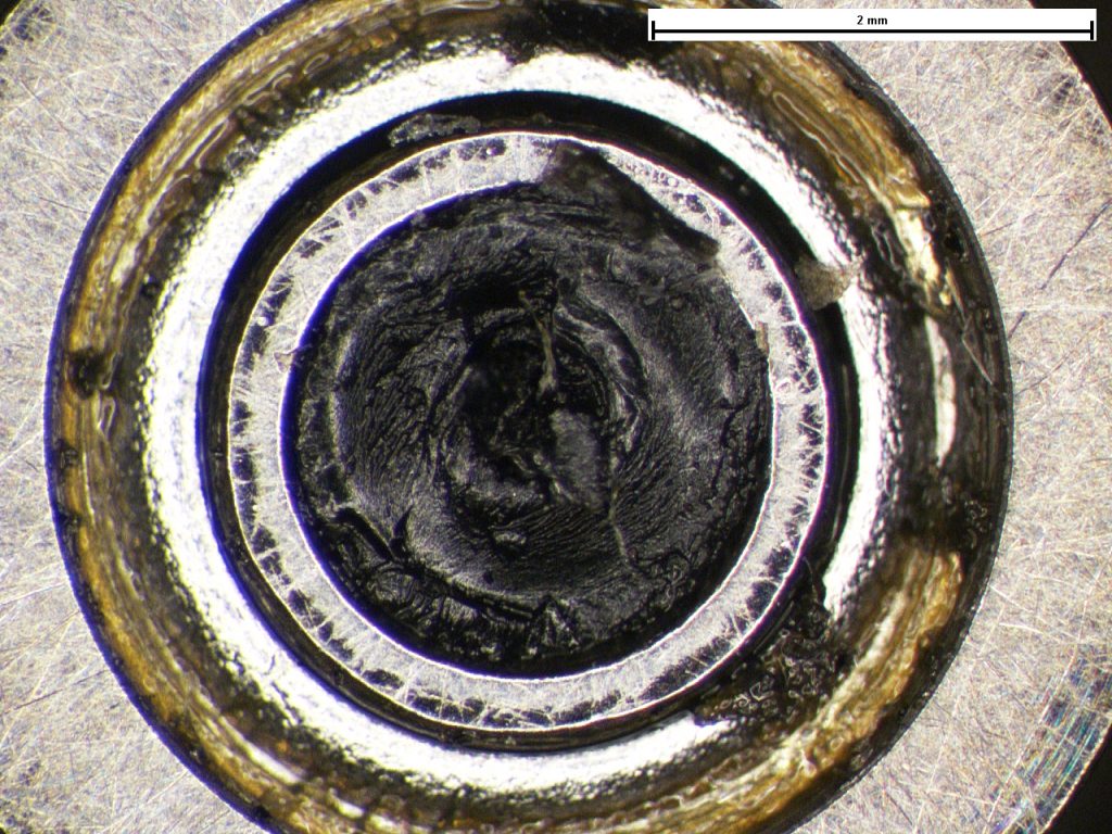


Fracture surface consistent with ESC.
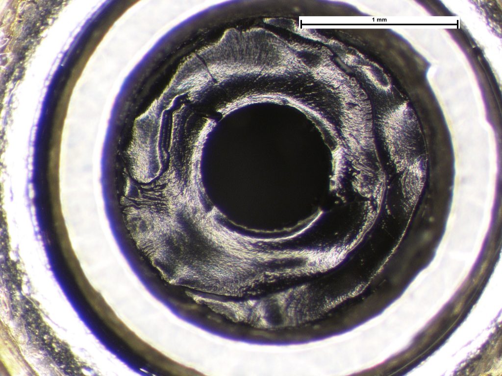


Fracture surface consistent with ESC.
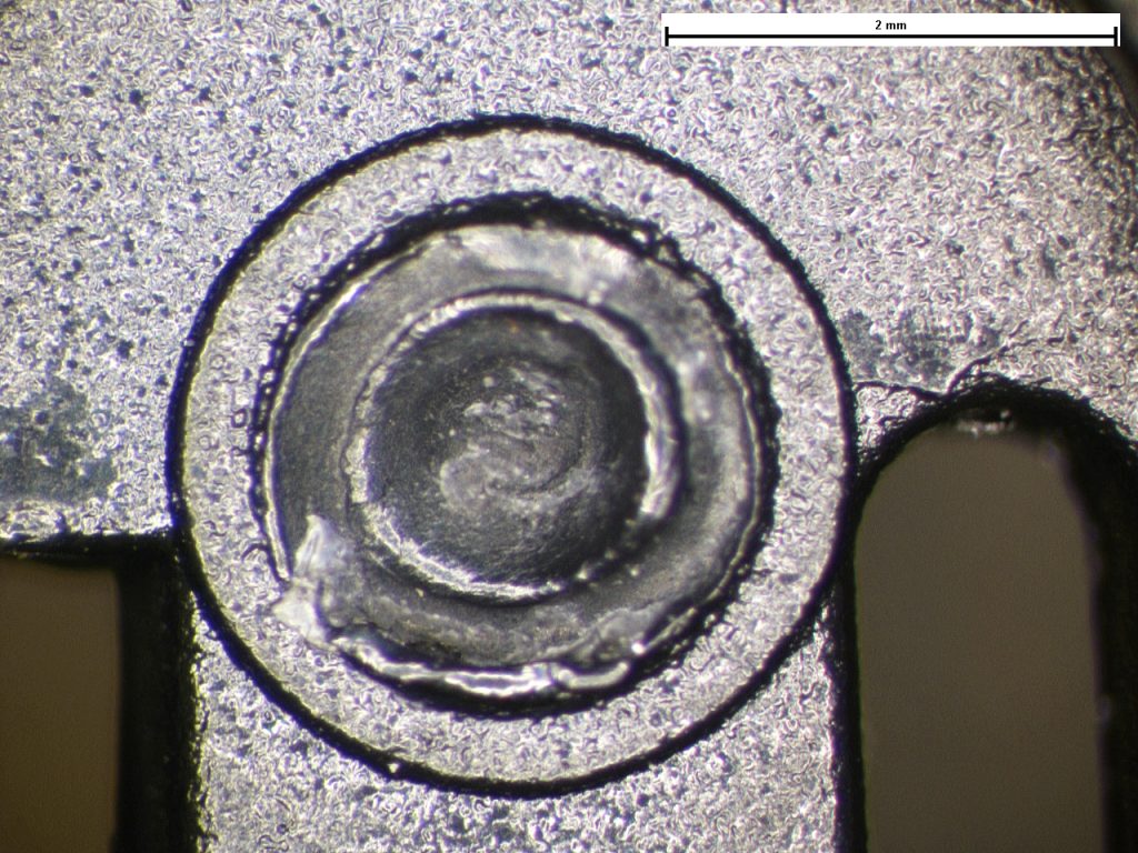


Tensile overload reference fracture.
Environmental Stress Cracking of Injection Moulded Pegs
Cracking of ~2mm Dia. pegs used in conjunction with a self tapping screw to secure bearings to a injection moulded PC-ABS component. The fractographic features revealed multiple coalescing brittle cracks indicative of environmental stress cracking (ESC). ESC was observed on both the samples with and without a self tapping screw revealing the ‘stress’ aspect to mostly be internal (residual). In-house tensile testing revealed fracture surfaces indicative of overload which were not comparable to the fractures of the samples taken out of service. Environmental stress cracking is the combination of a stress and an aggressive environment to a susceptible material. It was understood that the lubricant used within the bearing was hydrocarbon-based which is known to damage certain polymer materials and it is considered that compounds in the lubricant are the most probable source of this damaging environment. Although the self-tapping screw is likely to create additional hoop stress with the material, evidence of ESC was observed on both reference samples with and without the screws indicating the stress aspect is likely to be inherent within the material i.e. residual moulding stress and not from the fitment of the screws. If the aggressive environment (i.e. the lubricant) can be removed, then embrittlement in service is unlikely to occur.
Cracking in Welded Ductile Iron Pipe
Cracking in welded ductile iron pipe-flange sections. Leaks at the welds have been caused by brittle cracks that propagated thr...
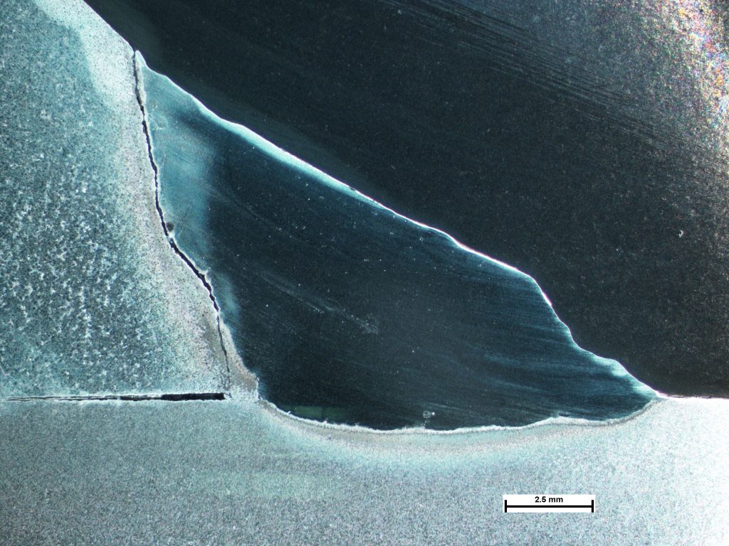


Section through the weld showing crack at fusion line.
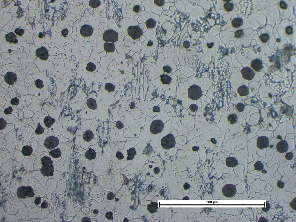


Photomicrograph of section through the pipe showing spheroidal graphite in a ferritic matrix, with isolated areas of pearlite and carbides. Image taken at X200 Mag.
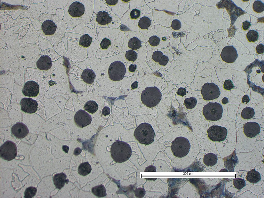


Photomicrograph of section through the flange showing spheroidal graphite in a ferritic matrix, with isolated areas of pearlite. Image taken at X200 Mag.
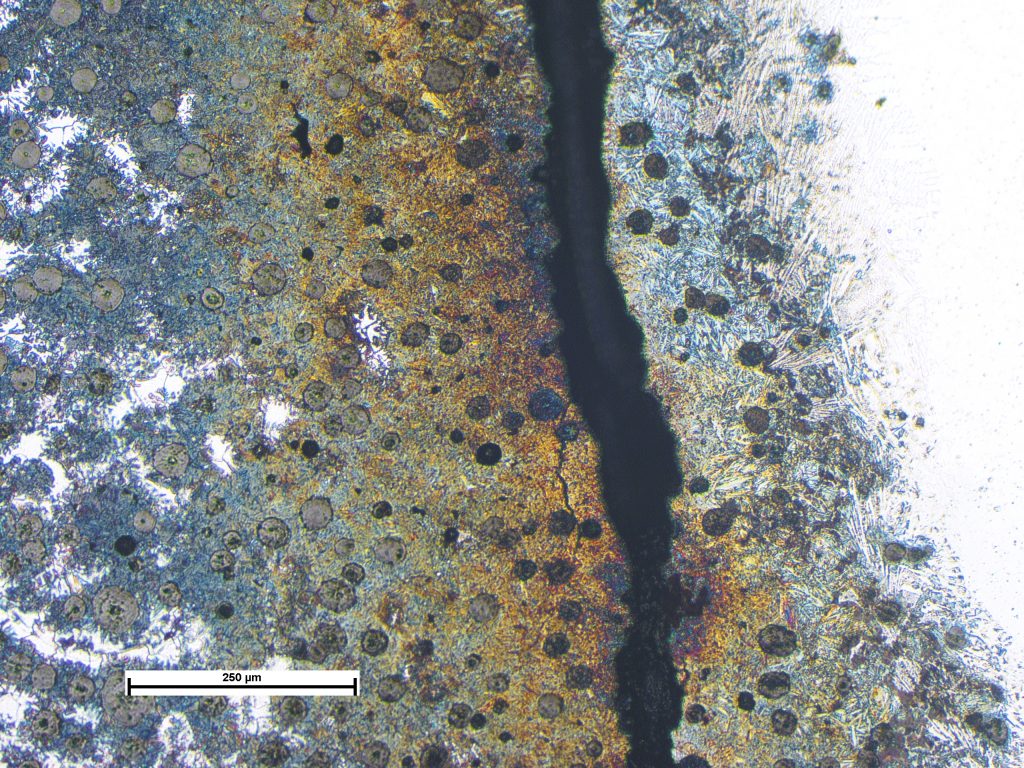


Photomicrograph of section through the crack at the fusion line, showing martensitic transformation in the weld heat affected zone. Image taken at X50 Mag.
Cracking in Welded Ductile Iron Pipe
Cracking in welded ductile iron pipe-flange sections. Leaks at the welds have been caused by brittle cracks that propagated throughout the weld heat affected zone (HAZ) of the flange components. Welding cast irons requires meticulous control of the welding parameters using appropriate procedures, as they are very susceptible to HAZ cracking such as that observed in the sample examined. The HAZ structures were coarse martensite with no evidence of tempering i.e. indicative of welding without preheat or post-weld heat treatment. The resulting martensitic structure is particularly brittle relative to the parent flange, pipe, and weld materials. Hardness testing supported this view, and that the welding parameters had been less than optimum, resulting in a hard and brittle HAZ. Stress to cause cracking results from contraction of the weld metal during cooling. The consumables used were typical for that used to weld cast iron, being nickel-rich.
Corroded Hydraulic Connector
Leaking hydraulic fitting used in a mining environment. Microscopic examination of the component revealed severe corrosion of ...
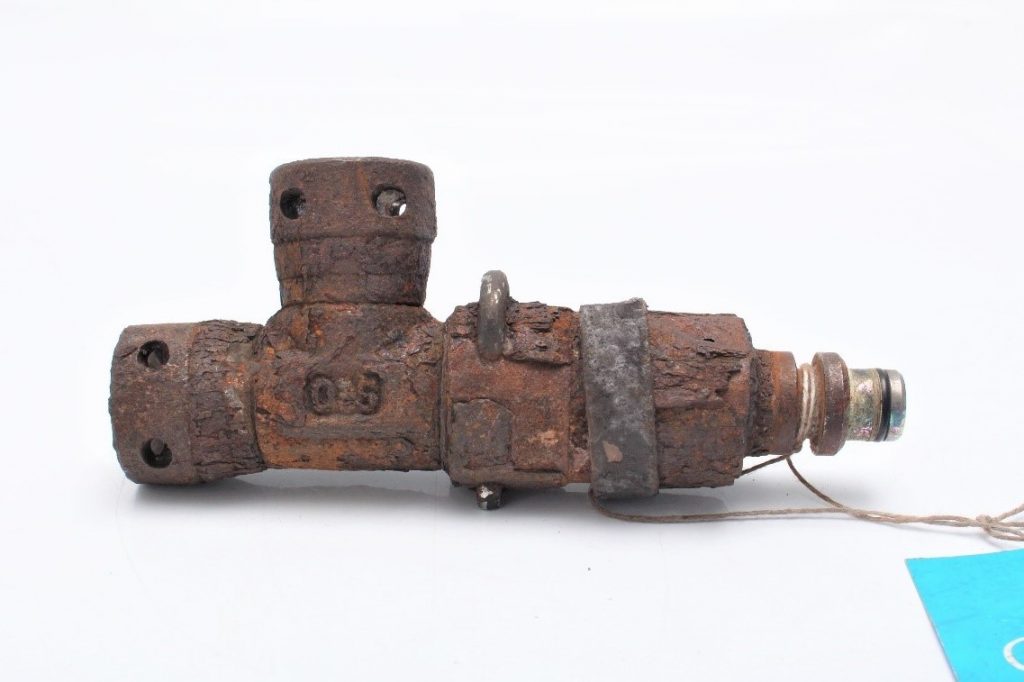


The sample as received.
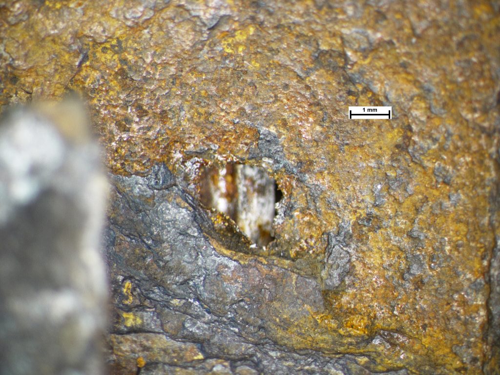


The ‘pinhole’ that caused the leak.
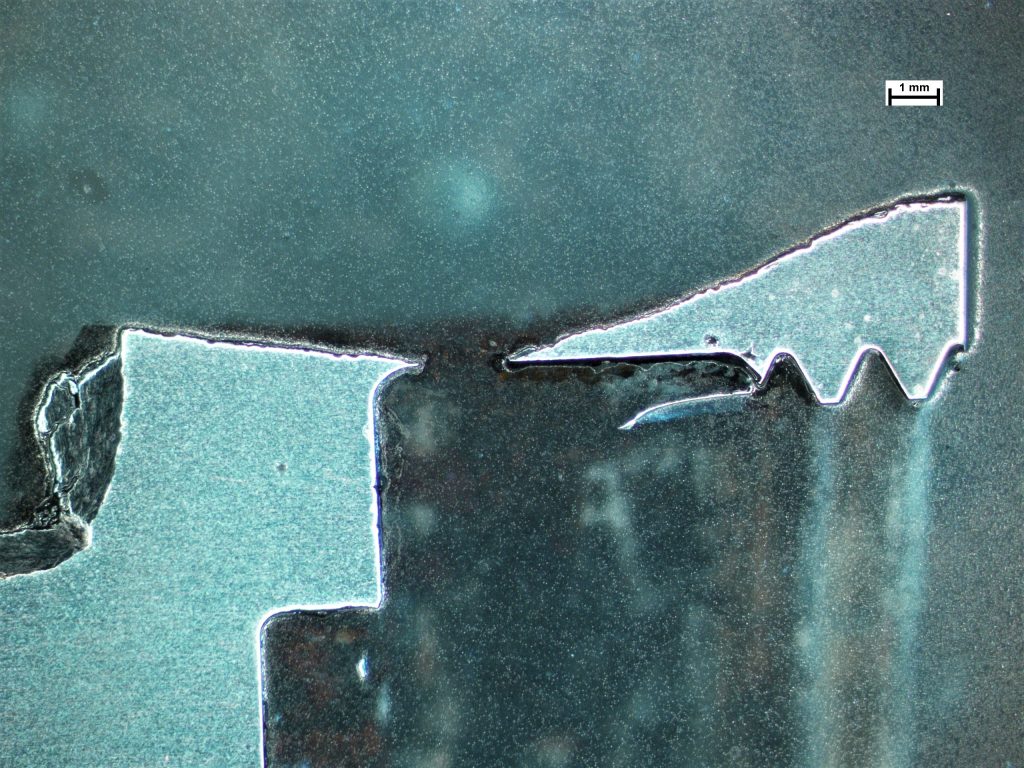


Mounted cross section revealing the reduction in the cross section.
Corroded Hydraulic Connector
Leaking hydraulic fitting used in a mining environment. Microscopic examination of the component revealed severe corrosion of the outer surface and minor corrosion on the inner surface. An EDX analysis was conducted on the corrosion product, and this detected high levels of chlorine which was likely to be in the form of chloride. Chloride is a known corrodent of materials such as steel and zinc. Corrosion had reduced the wall thickness to a point where one location had subsequently leaked.
Chrome Plating Corrosion
Examination shows that staining on the used ram is consistent with pitting corrosion and associated deposits. The chromium coatin...
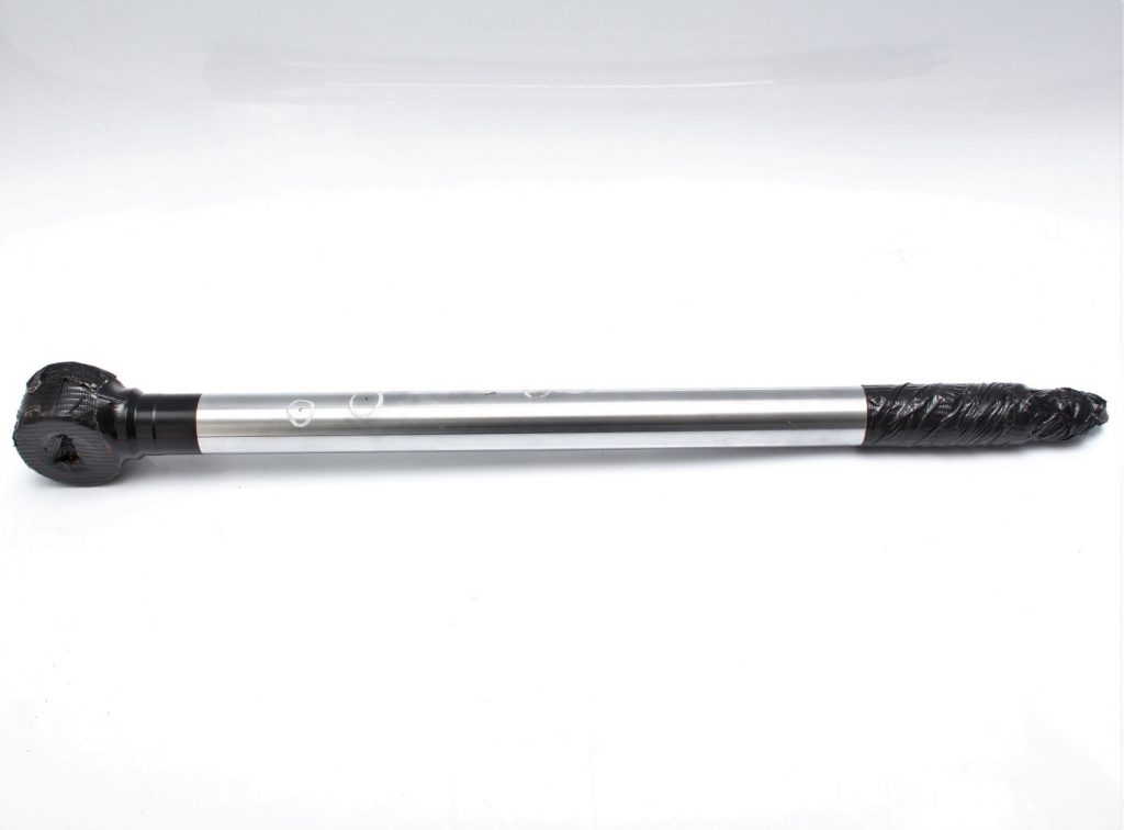


Used ram as received.
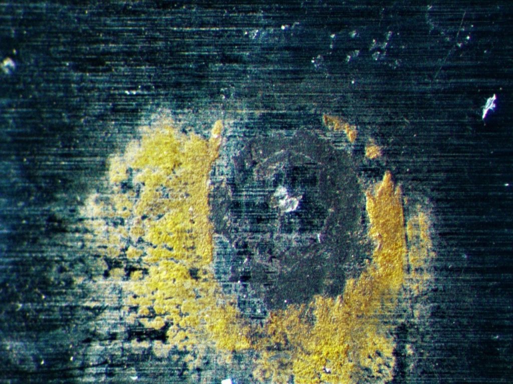


Corrosion pit and associated deposits.
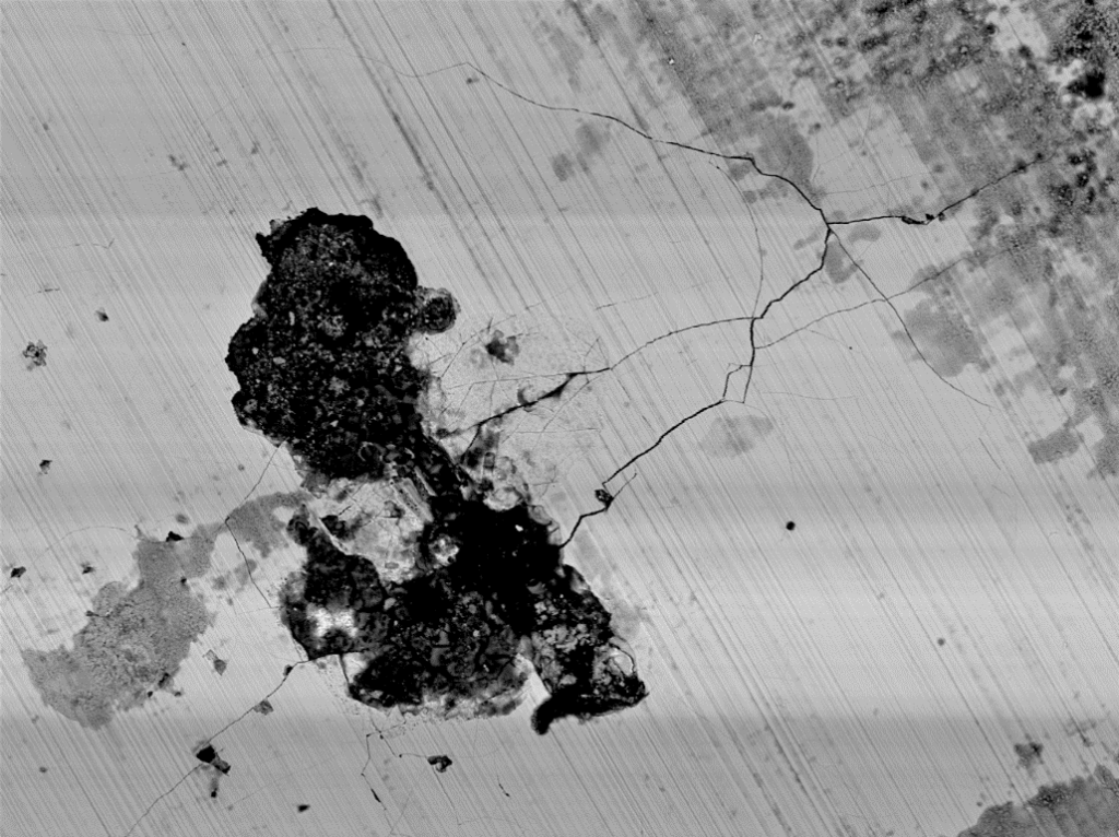


Localised cracking associated with a pit.
Chrome Plating Corrosion
Examination shows that staining on the used ram is consistent with pitting corrosion and associated deposits. The chromium coating is extensively cracked in the vicinity of the pits but not elsewhere. This cracking suggests that it was probably caused by the surface of the ram having been exposed to localised impact from a hard, sharp object. Since chromium is cathodic to the steel substrate, in the presence of an electrolyte, preferential corrosion of the steel is accelerated at the site of the damage, as observed. Used and the unused ram rods share similar hardness values and chromium coating layer thickness that were within specification.
Bronze Plating Exfoliation
Exfoliation and blistering of the bronze layer from a rod used in a hydraulic ram assembly. The presence of staining on the sur...
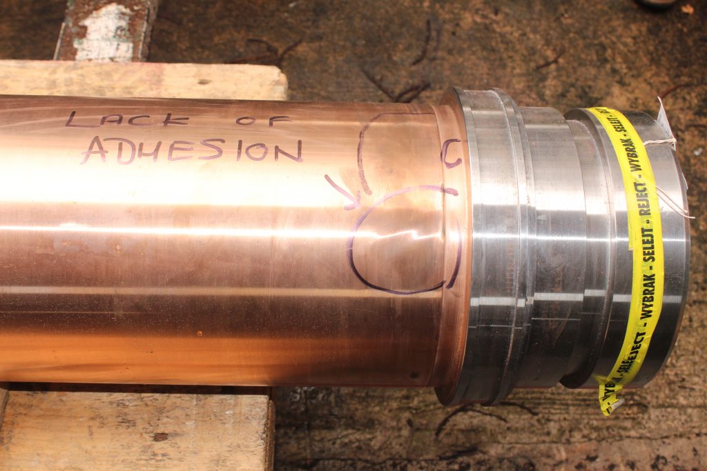


General surface with lack of adhesion.
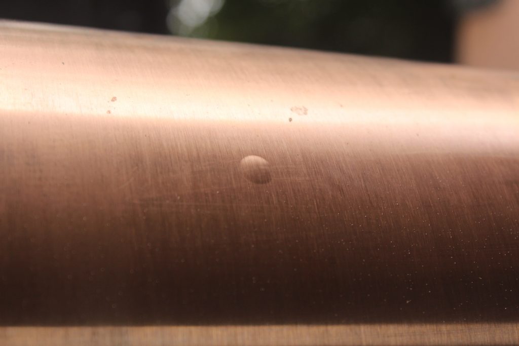


Blister observed in the central portion of the rod.
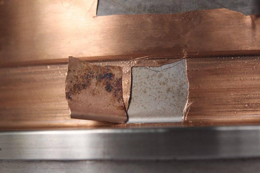


A lifted portion of plating revealing surface staining.
Bronze Plating Exfoliation
Exfoliation and blistering of the bronze layer from a rod used in a hydraulic ram assembly. The presence of staining on the surface of the steel substrate strongly indicated that the surface of the rod had not been adequately pickled/cleaned prior to plating. The staining was chemically analysed using the analysis function of the scanning electron microscope and was established to be carbon rich indicating it to be an organic substance. The organic substance likely formed a barrier that created the plating issues (lack of adhesion) observed.
Bearing Rolling Contact Fatigue
A rolling element bearing exhibiting rolling contact fatigue (RCF) spalling of the working surfaces. RCF was observed on the insid...
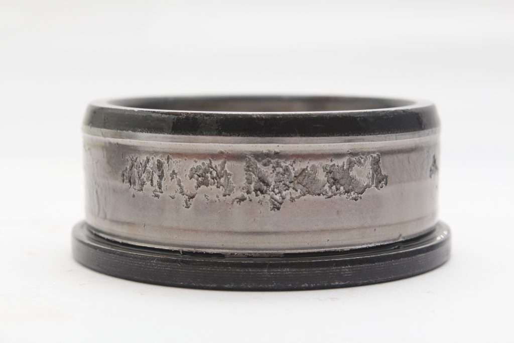


Bearing inner race surface.
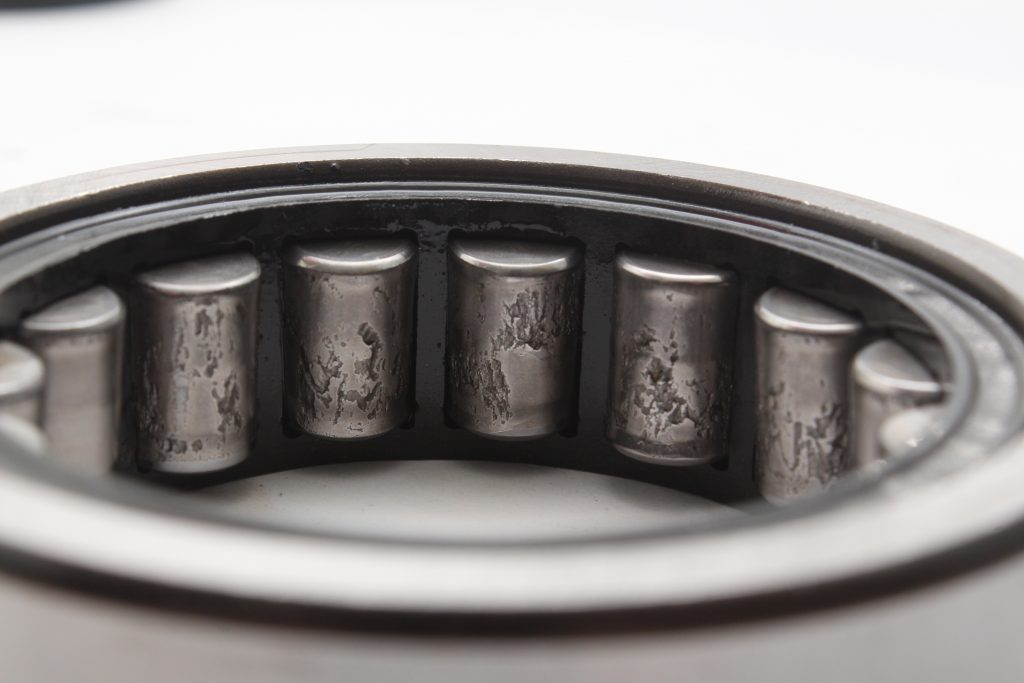


Bearing roller surfaces.
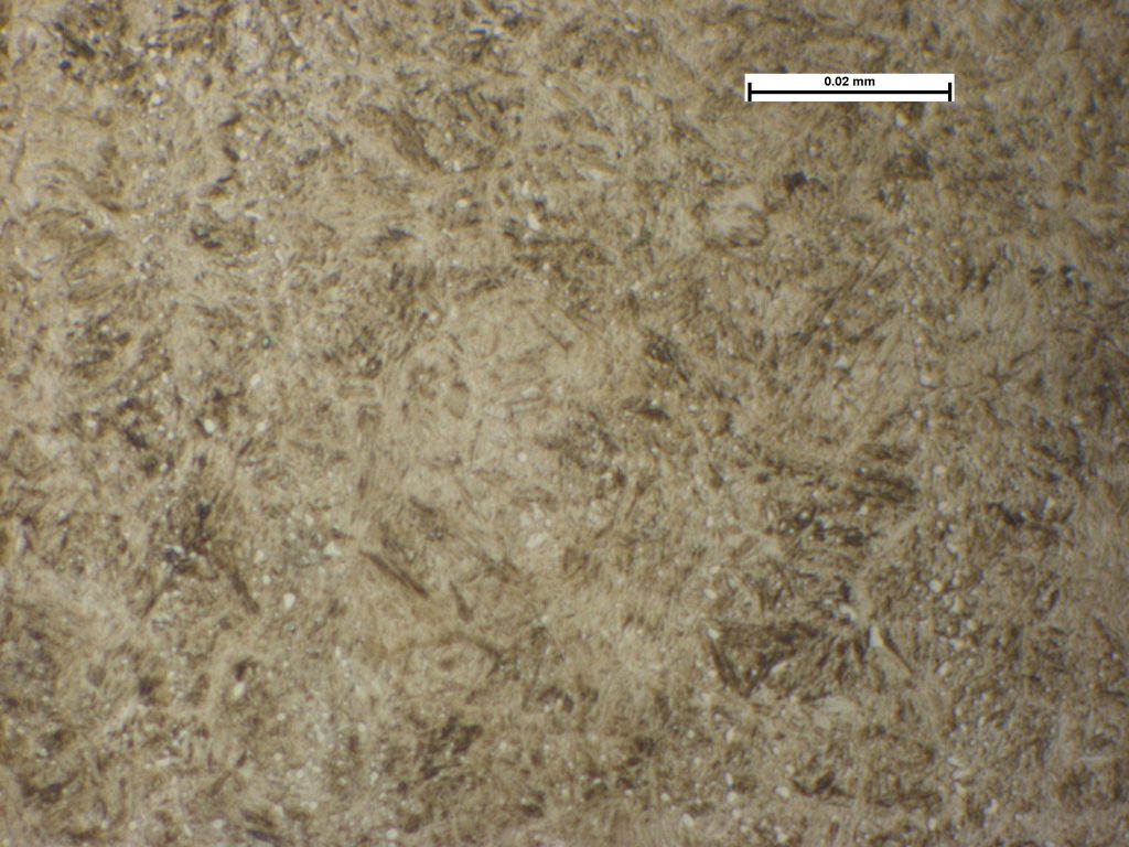


Photomicrograph revealing a fine-grained tempered martensite matrix and globular carbides. Image taken at X1000.
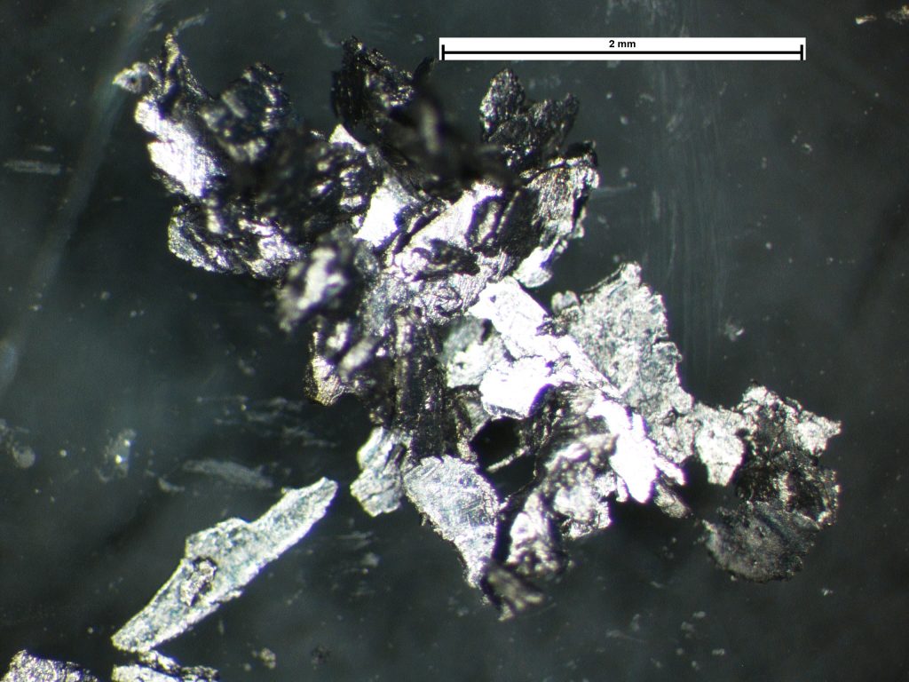


Debris gathered from the oil filter. Image taken at X25.
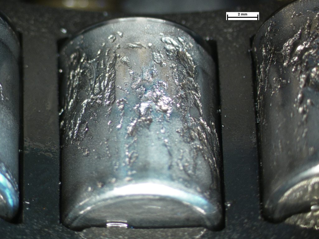


Macroscopic view of the bearing surface displaying a scalloped surface. Image taken at X6.
Bearing Rolling Contact Fatigue
A rolling element bearing exhibiting rolling contact fatigue (RCF) spalling of the working surfaces. RCF was observed on the inside and outside race as well as the bearings. Hardness surveys revealed the races to be of the same hardness as the rolling elements; maximum fatigue life is achieved when the rolling element is approximately one to two points (Rockwell C) harder than the races. The bearings were later established to be counterfeit.
Ball Plate Cracking
Most of the cracks visible on the surface propagated radially from the outer corner of the working face into the body of the casti...
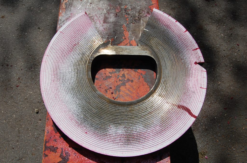


The working face following Dye Penetrant crack detection.
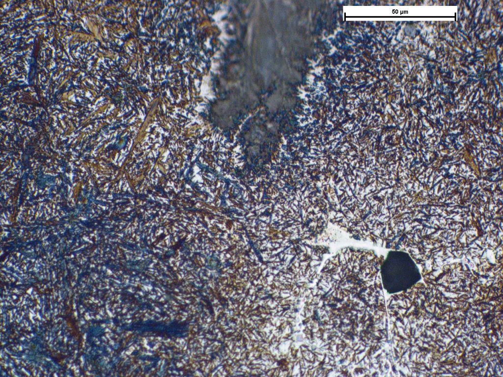


The matrix microstructure. Image taken at X500.
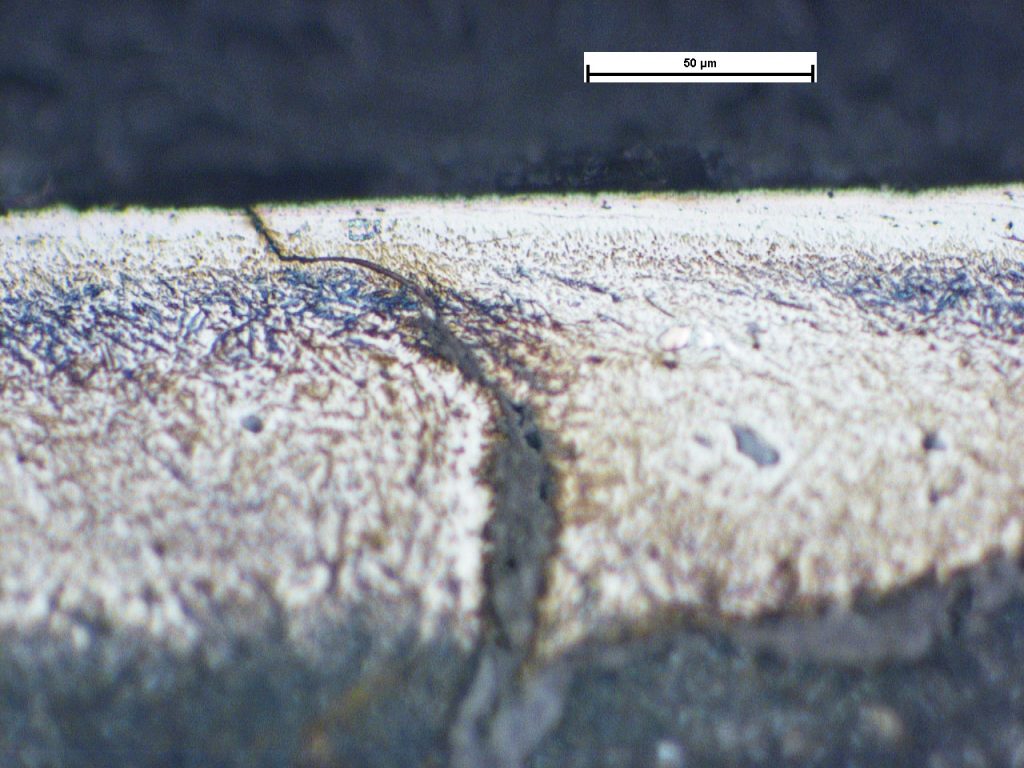


‘White layer’ surface conversion. Image taken at X200.
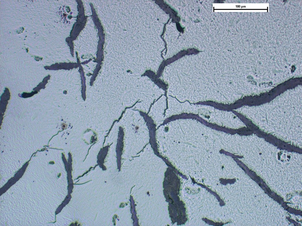


Isolated subsurface cracks in the matrix. Image taken at X200. Sample as polished.
Ball Plate Cracking
Most of the cracks visible on the surface propagated radially from the outer corner of the working face into the body of the casting. This is consistent with tensile hoop stresses; the open nature of the cracks indicated that the stresses were high. It is possible that some out-of-plane bending whilst in service could have also contributed to the crack propagation although this is considered as a secondary driver of the observed cracking. Cracking was predominantly located in the martensitic matrix whereas grey cast irons exposed to tensile stress normally crack along graphite flakes with cracks propagating from flake to flake. In this case the cracking of the matrix indicated that stress was sufficient to have resulted in multiple small cracks. As service use would not be expected to result in such cracking, locked-in, residual manufacturing stress was the most likely culprit. Such residual stresses are not uncommon from casting and associated processing, e.g. heat treatment.
 Account

